Installation – Montigo H38DF ST User Manual
Page 14
H*38DF ST Indoor Gas Fireplace
Page 14
XG0207 - 150204.1
Installation
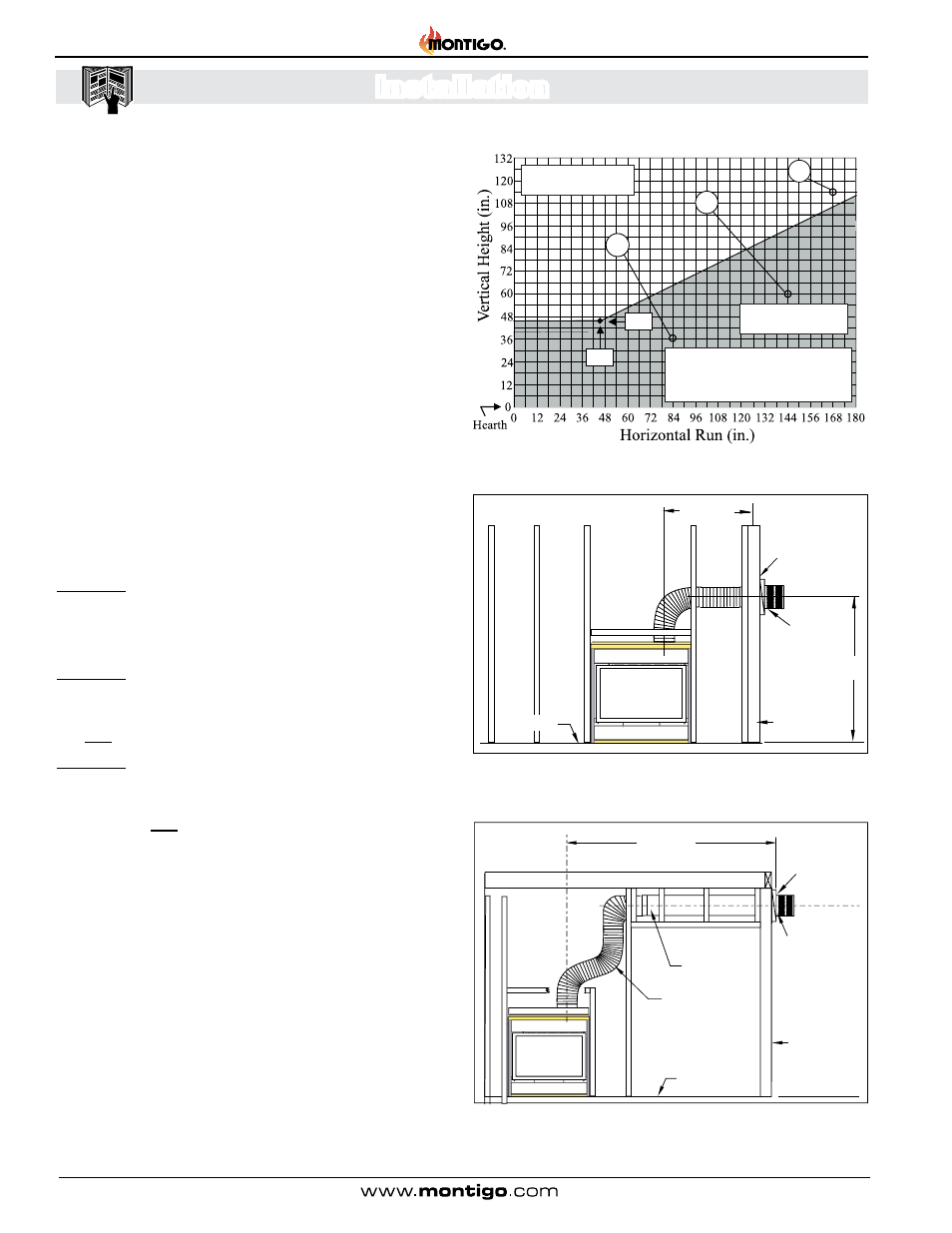
The Venting Graph:
Measure the vertical height from the fireplace hearth to the centre of the
termination and the horizontal run from the fireplace flue collar to the wall
flange of the termination. Plot on the Venting Graph Figure 13 with an 'X'.
If the 'X' falls on or above the top boundary of the shaded area, the
installation is acceptable.
Example A: (Acceptable Installation)
If the vertical dimension from the hearth is 114" and the horizontal
run to the wall flange of the vent termination is 168", this would be
an acceptable installation.
Example B: (Unacceptable Installation)
If the vertical dimension from the hearth is 36" and the horizontal
run to the wall flange of the vent termination is 84", this would
NOT be an acceptable installation.
Example C: (Unacceptable Installation)
If the vertical dimension from the floor of the fireplace is 60" and
the horizontal run to the wall flange of the vent termination is 144",
this would NOT be an acceptable installation.
Figure 13. Top Vent Venting Graph for wall mounted terminations.
Figure 13a. Top Vented, wall mounted installation with one 90° bend. The vent
run must comply with Venting Graph for Top vent, wall mounted terminations,
Figure 13.
Figure 13b. Top Vented, wall mounted Multi-elbow installation. See Venting
Graph for Top vent, wall mounted terminations, Figure 13.
Section 3-3-1: Venting Layout: Wall mounted termination.
Selection of components and details of venting layout should adhere
to the following guidelines:
Vent terminations must not be recessed in walls or siding.
For Heat Shield requirements see Section 3-3-3.
Once the proposed venting layout has been determined refer to
Figure 13 or 14 to ensure the layout is acceptable.
Notes Wall Mounted Terminations: TOP VENT
All measurements for vertical or horizontal runs are measured
from center of the vent pipe.
Venting runs must fall within the limits set by the venting graph,
see Figure 13.
42”
46”
A
C
B
Unacceptable vent run
within shaded area.
Acceptable vent run
within non-shaded area.
If your installation does not fall within
the venting graph parameters,
please contact a local Montigo dealer
for Power Venting Options.
Heat Shield
42” Max.
46”Min.
Termination
Exterior
Wall
Hearth
Solid Section
Flex Section
Hearth
15’ foot Max.
Heat
Shield
Termination
Exterior
Wa
ll