Installation, Conduit & wiring clearances – Montigo R320-ST User Manual
Page 19
115
R1 R2 R3
R1
R2
Light
PV
Plug
PV Speed
Controller
Ye
llo
w
Ye
llo
w
Blac
k
Blue
Blu
e
Br
ow
n
Yellow
Blue
Black
White
White
1
2
3
4
5
Combustion
Air
Flue
Gas
Wall
Switch
Orange
Whi
te
Black
B
lk
/W
ht
Wht/Blk
Blue
R
ed
B
ro
w
n
NC
Combustion
Air
NO
Flue
Gas
ELECTRICAL CONTROL PANEL
R3
Gas
Valve
Wall
Switch
Fuse
110 Volts
60Hz
5A
Post Purge
Timer
Pre-Purge
Timer
Honeywell (Q3450)
Pilot Assembly
Pilot Electrical
Harness Connector
Honeywell Gas
Control (SV9501M)
Gas Control
onnector
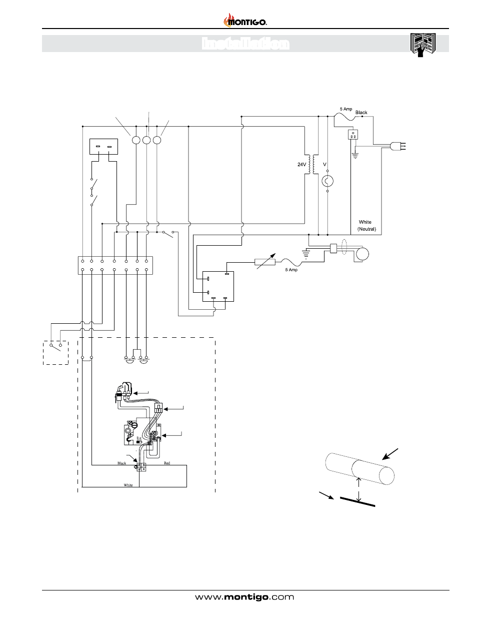
Conduit & Wiring clearances
1” Clearance
Note:
If any of the original wire supplied with the appliance is
replaced, it must be with the same or its equivalent.
Connect the power vent power cord as outlined in the
previous section. Ensure that the proper clearances are
maintained for the wiring and conduit. When installing the
wiring it must never run above the vent run and it must be
at least 1” clear of all venting.
Vent pipe
Figure 5 Sec.5 R320ST* / R420ST* Wiring Diagram
Figure 6 Sec.5 Conduit and Wiring Clearances
R320-ST & R420-ST Power Vent Indoor Gas Fireplace
Page 19
XG0774 - 150121
Installation