2 mechanical installation, Caution, 1 main unit installation – ONICON System-30 MODBUS BTU User Manual
Page 10
11451 South Belcher Road, Largo, FL 33773 • USA • Tel +1 (727) 447-6140 • Fax (727) 442-5699 • [email protected]
System-30 BTU Measurement System MODBUS RTU RS485 04/14 - 0583-1 / 18345
Page 10
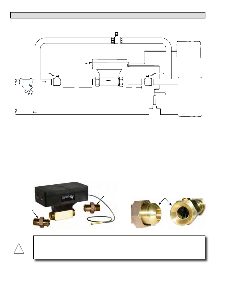
3.2 MECHANICAL INSTALLATION
3.2.1 Main Unit Installation
SYSTEM-30 BTU MEASUREMENT SYSTEM WITH INTEGRAL
FLOW METER & TEMPERATURE SENSORS
0333-2
INCORPORATED
ISOLATION VALVE
Normally Open
ISOLATION VALVE
Normally Open
BYPASS VALVE
Normally Closed
20"
5"
CHILLED WATER
SUPPLY
Y Strainer Upstream
Of Flow Meter
CHILLED WATER
RETURN
CONTROL SYSTEM
BACnet MS/TP
NETWORK
24 VAC POWER
FAN COIL UNIT
OR
AIR HANDLING UNIT
1500 North Belcher Road, Clearwater, FL 33765 • Tel (727) 447-6140 • Fax (727) 442-5699
www.onicon.com • [email protected]
01-13-09
RETURN TEMP
FLOW
DIAGNOSTIC
LED’S
CONTROL SYSTEM
MODBUS RTU
NETWORK
24V AC/DC
!
CAUTION
Before you attempt to use the BTU measurement system, isolate the main unit, open the bypass
and flush the entire system so that it is free of flux, solder, pipe and tube cuttings and any other
free moving particles.
Installing the meter body
1. Make sure the unions are free of nicks or scratches on either end of the flow
meter body and on the process connections.
2. Spray the union faces with a silicone spray or apply a thin coat of beeswax to enhance
seating. Do not use paste thread sealant on union faces.
3. Orient the flow arrow on the meter with the direction of flow.
4. Recommended torques for union seal: 70 ft/lbs minimum
5. Make sure alignment of pipe does not put lateral stress on either joint.
Process
Connection
Process
Connection
Unions