ONICON System-30 MODBUS BTU User Manual
Page 14
11451 South Belcher Road, Largo, FL 33773 • USA • Tel +1 (727) 447-6140 • Fax (727) 442-5699 • [email protected]
System-30 BTU Measurement System MODBUS RTU RS485 04/14 - 0583-1 / 18345
Page 14
It is often desirable to totalize the amount of energy transferred in each mode in separate registers.
For these applications, ONICON BTU meters may be configured for dual mode operation. In this
configuration, the meter will measure and totalize energy in separate registers based on the
polarity of the Delta t.
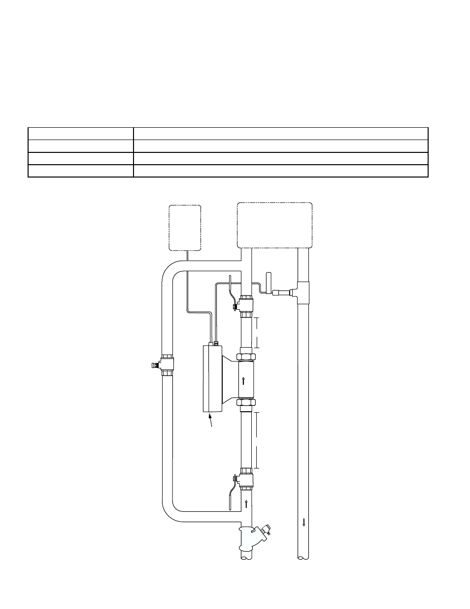
The drawings and tables below illustrate the relationship between meter location, temperature
sensor and mode of operation.
Temperature Sensor/ Mode of Operation Relationship with Meter in Supply Line
Supply Temp
Temperature 1 Sensor (Internal Sensor)
Return Temp
Temperature 2 Sensor (External Sensor)
Mode 1 Total
Heating (Supply Temp > Return Temp)
Mode 2 Total
Cooling (Supply Temp < Return Temp)
SYSTEM-30 BTU MEASUREMENT SYSTEM WITH INTEGRAL
FLOW METER & TEMPERATURE SENSORS
0333-2
INCORPOR
A
TE
D
ISOLATION VALVE
Normally Open
ISOLATION VALVE
Normally Open
BYPASS VALVE Normally Closed
20"
5"
CHILLED W
ATER
SUPPL
Y
Y Strainer Upstream
Of Flow Meter
CHILLED W
ATER
RETURN
CONTROL
SYSTEM
BACnet MS/TP
NETWORK
24 V
AC POWER
FAN COIL
UNIT
OR
AIR HANDLING UNIT
1500 North Belcher Road, Clearwate
r, FL
33765 • T
el (727) 447-6140 • Fax (727) 442-5699
www
.onicon.com • [email protected]
01-13-09
RETURN
TEMP
FLOW
DIAGNOSTIC
LED’S
CONTROL
SYSTEM
MODBUS R
TU
NETWORK
24 V
AC POWER