ONICON System-30 MODBUS BTU User Manual
Page 36
11451 South Belcher Road, Largo, FL 33773 • USA • Tel +1 (727) 447-6140 • Fax (727) 442-5699 • [email protected]
System-30 BTU Measurement System MODBUS RTU RS485 04/14 - 0583-1 / 18345
Page 36
4.8 DIAGNOSTICS
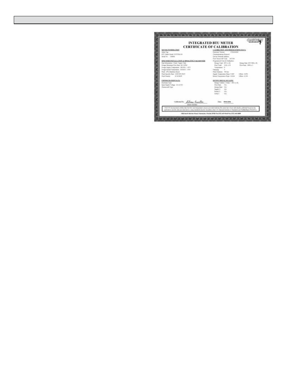
The ONICON System-30 BTU MEASUREMENT
SYSTEM uses a microprocessor to calculate
energy. Factory programmed settings provide
energy total outputs in accordance with the
customer’s application data. An optional
isolated analog output for energy rate, flow rate
or delta T may also be available. Refer to the
Btu meter calibration sheet for a complete listing
of factory settings. These settings cannot be
changed in the field. Contact ONICON factory
service personnel if changes to the calibration
are required.
The System-30 is equipped with diagnostic
indicator lights that confirm the operation of
the microprocessor and its input circuitry.
Please contact the ONICON factory service personnel if either of the diagnostic lights
indicate a potential problem with the operation of the BTU MEASUREMENT SYSTEM.
4.8.1 Diagnostic Lights
Energy
Located on the end of main unit opposite the cable connection is a red LED labeled Btu.
This LED will flash as energy is transferred.
Liquid Flow
Located on the end of main unit opposite the cable connection is a red LED labeled FLOW.
This LED will flash at a rate that is proportional to the liquid flow rate. An unlit LED
indicates no flow signal.