Rear panel connectors, Xr-series rear panel, 8/16 channel hvr – OpenEye OE4 User Manual
Page 18
6
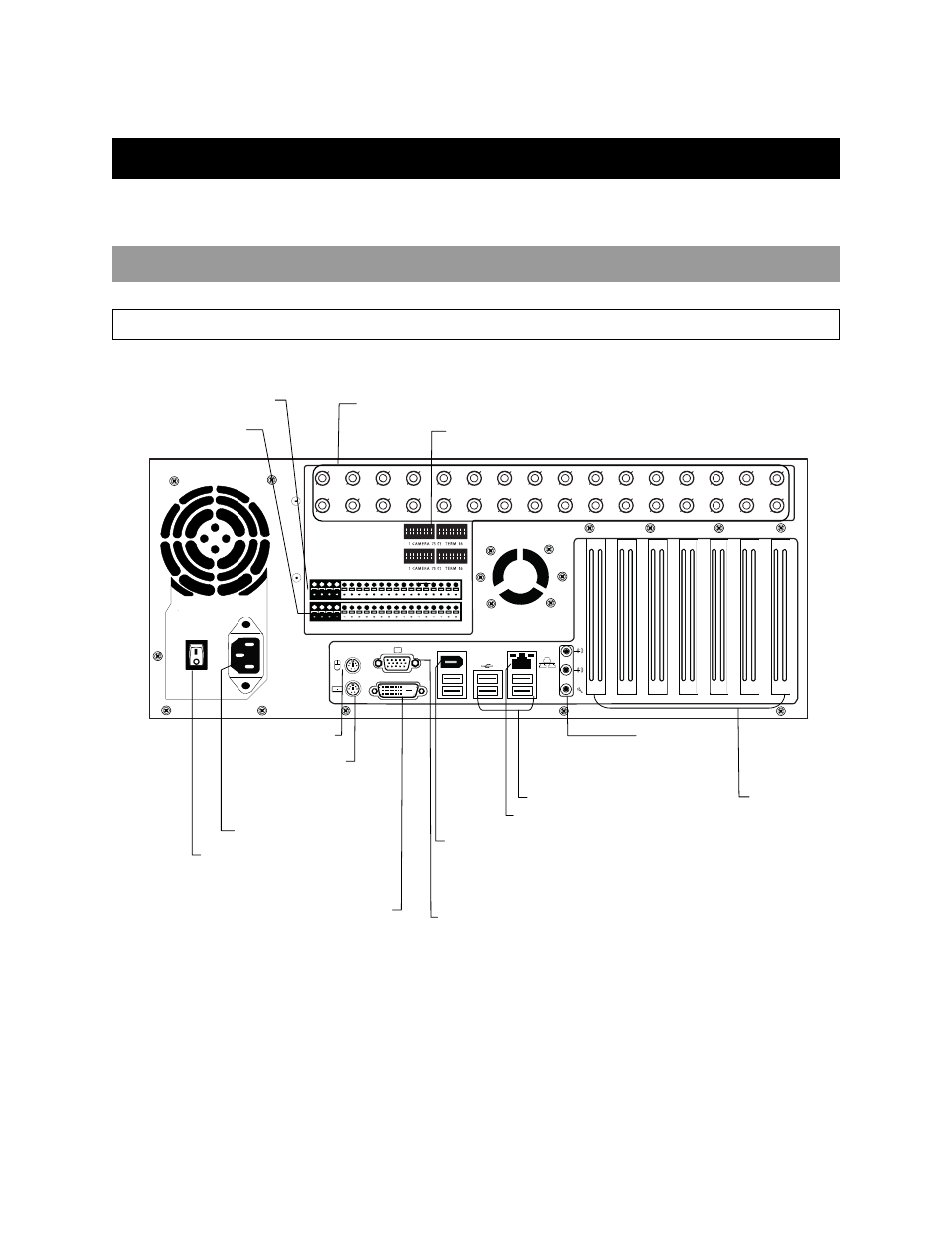
REAR PANEL CONNECTORS
The rear panel of the HVR contains the connectors used to attach cameras, sensors, and relays to the HVR. Below are diagrams that
outline the location and description of each connector:
XR-SERIES REAR PANEL
8/16 Channel HVR
CH 1 in
CH 2 in
CH 3 in
CH 4 in
CH 5 in
CH 6 in
CH 7 in
CH 8 in
CH 9 in
CH 10 in
CH 11 in
CH 12 in
CH 13 in
CH 14 in
CH 15 in
CH 16 in
1 2 3 4 5 6 7 8 9 10 11 12 13 14 15 16
CONTROL
1 2 3 4 5 6 7 8 9 10 11 12 13 14 15 1
6
COM
SENSOR
ON
OFF
ON
OFF
DVI-D
1394
CH 1 Out
CH 2 Out
CH 3 Out
CH 4 Out
CH 5 Out
CH 6 Out
CH 7 Out
CH 8 Out CH 9 Ou t
CH 10 Out
CH 11 Out
CH 12 Out
CH 13 Out
CH 14 Out
CH 15 Out
CH 16 Out
Looping Termination Switch
BNC Connectors for Video Input / Looping Output
Control Alarm Outputs
Sensor Inputs
AC Power Connector
Secondary Power Switch
PS/2 Mouse Input
PS/2 Keyboard Input
DVI-D Port
SVGA Output
Fire Wire (w/ RAID only)
RJ-45 Network Jack
USB Ports
Audio
• Line In
• Speaker Out
• Mic In
PCI Options