Ravenheat CSI 85 User Manual
Page 21
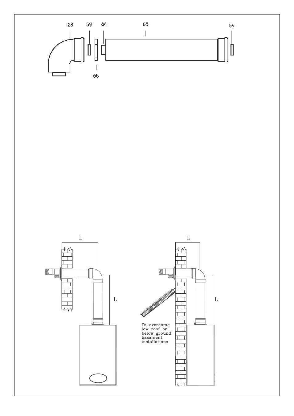
KEY
59 - Rubber seal diam. 60
63 - Air intake duct extension
64 - Flue exhaust extension
65 - Pipe centering spring
128 - In line bend
21
- Remove the centering spring 65, pull the
flue terminal, disengage inner flue duct.
- Measure the thickness W of the wall.
- Cut the outer air duct (100 mm. dia.) at right
angles and to a length equal to W+Y - 47
mm. (fig. 18).
- Cut the inner flue duct (60 mm dia.) at right
angles and to a length equal to W+Y + 65 mm.
- Outer air duct and inner flue duct must be
de-burred.
- Reassemble the two tubes.
Insert centering spring 65.
5.7.5
Insert the flue assembly into the wall, making
sure it will not interfere when fixing the boiler
on the wall.
5.7.6
Lift the boiler on to the wall. Locate onto
the top coach bolts. Fit the lower coach
bolts and tighten all four securing bolts.
5.7.7
Working above the boiler pull the flue duct
towards the elbow in order to engage tube into
its header (Fig. 21). Position flue into straight
header and push to locate inner and outer
flue correctly. Ensuring good seal is made
with o.rings.
5.7.8
Extension kits are available to order for flue
extension of up to 2.5 metres total length
(Fig. 19). For further details see sect 5.5.9.
Fig. 27
Fig. 26
VERTICAL FLUE INSTRUCTIONS ONLY
L + L = 3.25 m MAX