Ravenheat CSI 85 User Manual
Page 36
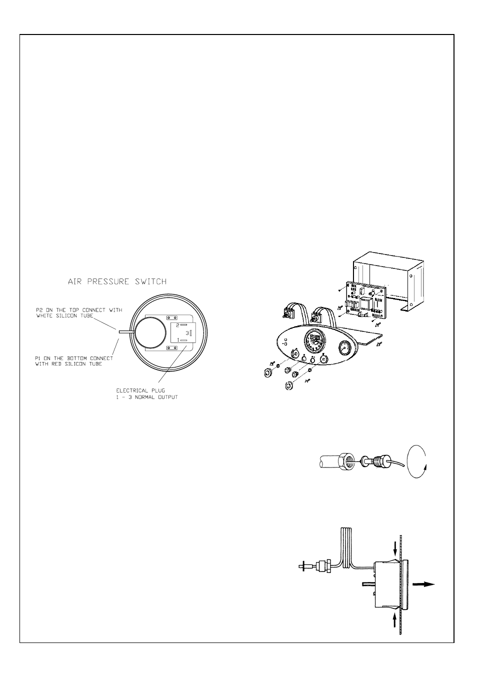
7.18 TO REMOVE/REPLACE THE WATER
PRESSURE GAUGE (Fig. 54).
7.18.1 Remove front casing (sect 7.3).
7.18.2 Close the on/off valves for the heating
circuit and drain the water at the drain point
(fig. 45).
7.18.3 Unscrew the fitting that secures the
pressure gauge probe.
7.18.4 Remove the pressure gauge from the
instrument panel by pressing its fastening
springs.
7.18.5 Replace in reverse order.
New seal must be used.
36
7.19 TO REMOVE/REPLACE THE ELECTRIC
CONTROL AND IGNITION BOARD.
7.19.1
Remove the front panel from the outer
casing (sect. 7.3) and lower the instrument
panel .
7.19.2 Unscrew the 2 screws holding the control box
box cover and remove.
Disconnect mains cables and any other
connections (room thermostat).
7.19.3 Detach the connectors from the board.
7.19.4 Replace in reverse order (ensure all electrical
connections are made correctly).
7.17
TO REMOVE/REPLACE THE DIFFERENTIAL
PRESSURE SWITCH (fig. 52).
7.17.1 Remove front casing (sect. 7.3).
7.17.2 Detach the wire connector plug from the
pressure switch, make sure that the wire
connector plug are later reconnected.
7.17.3 Unscrew the two screws that fasten the pressure
switch to the back of the combustion
chamber.
7.17.4 Remove the two silicone tubes.
7.17.5 Ensure tubes are connected correctly (Fig. 52)
avoiding kinks.
7.17.6 Replace in reverse order ensuring that the
“–” tapping is connected to the tube
terminating inside the case and the “+”
tapping is connected to the tube terminating at
the flue ring.
Fig. 53
Fig. 54
Fig. 52