Ravenheat CSI 85 User Manual
Page 22
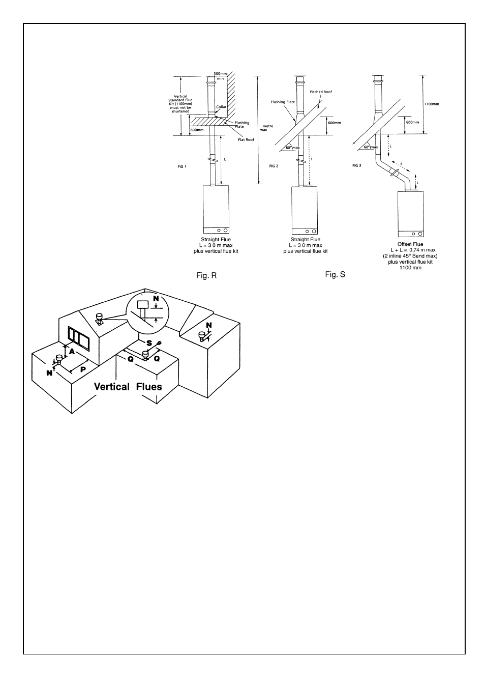
Fig. 28
Fig. 29
22
5.7.9
VERTICAL FLUE INSTRUCTION ONLY.
IN LINE FLUE BEND - 1680 mm MUST BE DEDUCTED FROM OVERALL LENGTH FOR EACH 90° BEND
OBTUSE FLUE BEND - 1680 mm MUST BE DEDUCTED FROM OVERALL LENGTH FOR EACH 135° BEND
The vertical flue kit is intended
for use where a horizontal flue
outlet is not possible or desired
The vertical flue can be used
either with a flat roof or a
pitched roof (maximum pitch
60°) Where a straight vertical
flue is not possible or desired,
an offset vertical flue can be
used in conjunction with a side
horizontal flue extension piece
and an inline 135°/90° flue
bend (Fig. 27 - 28).
POSITION
MIN. DISTANCE mm
N above roof level (to base of terminal)
300
P from adjacent wall to flue
300
Q from internal corner to flue
300
S from facing terminal
1,200
M horizontally from a vertical terminal to a wall 300
Before proceeding with installation check the contents
of the RAVENHEAT VERTICAL FLUE KIT, comprising
of the following pieces:
- 1 RAVENHEAT VERTICAL FLUE
complete with terminal assembly (for vertical
flue application).
- Additional 1000 mm (approx) Flue Extension
pieces as necessary, each extension is
provided with flue centering bracket.
- One box containing straight header with inlet
and outlet sealing rings.
Proceed with installation as detailed in section 5, of the
main Installation and Servicing Instruction, ignoring
all references to horizontal flue installations.
Use adhesive tape to attach the template to the wall,
making sure that the centre line is vertical and that the
flue centre line is vertically below the point at which the
flue will exit the roof.
- Ensure that the maximum permissible flue
length is not exceeded (fig. 29).
- Mark the four boiler fastening holes on the
wall.
- Detach the template from the wall.
- Use a 10 mm dia. drill to make the 4 boiler
securing holes. Insert plastic expansion
plugs (fig. 16).
- Screw in the two upper coach bolts leaving
them about 10 mm out from the wall to
enable the boiler to be located on the wall.
- Position the straight header on the top of the
appliance (fig. 31) item 6, and ensure that
the gasket is correctly fitted.
Important: Make sure that the flue header dia
60 mm duct is inserted fully into the fan spigot.
Starting at the appliance end, assemble the
extension duct sections, making each inner and
outer (flue) joint by inserting the spigot end into
the socket end of the next tube, making sure
the seal rings are correctly located (Fig. 30).
Make sure that the entire flue is adequately
supported. Use at least one bracket for each
extension used.
Ensure that all inner flue connections have a
good fit/seal, and that the space clips in each
extension are correctly positioned.