Ravenheat CSI 85 User Manual
Page 44
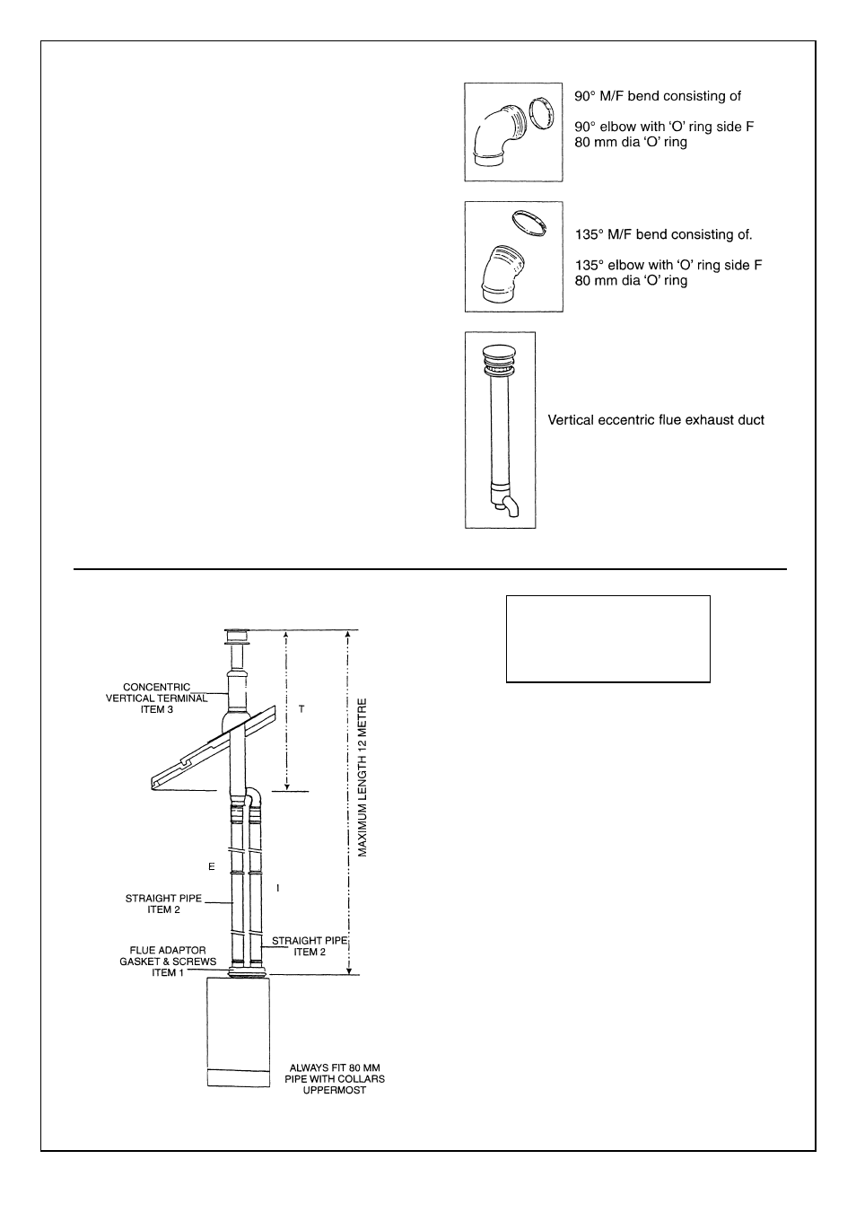
E = EXHAUST
I = INLET
T= TERMINAL
44
Locate the sealing washer fi xing the twin fl ue
header as illustrated making sure that the
inner aluminium exhaust locates fi rmly in the
outlet spigot make sure that the screws are
satisfactorily located through the gasket seal.
Locate the 2 x 80 mm ‘O’ rings in the twin flue
header.
Figures show the versatility of this flue system.
Measurements and bends must be calculated
correctly so as not to oversize maximum flue
lenght.
All located ‘O’ rings must be lubricated with a
silicone grease to ensure easy, snug fit.
NOTE: Exhaust flue must slope 2° down towards
the boiler 35 mm fall per metre.
Spacing Clips
Spacing Clips are available on request should
they be required.
NOTE: for eccentric vertical flue a 125 mm (5 in)
diameter flashing plate will be required.
Exhaust/suction system with concentric pipes for fl at or
sloping roofs. Extensions with two separate pipes.
Maximum distance = I + E + T = 2 Metre + 2 Metre + 1
Metre = 12 Metre maximum (pipe + terminal).
Minimum distance D = T = 2 metre.
Exhaust terminal must not be cut.
NOTE- The pressure loss for each elbow fi tted is:
90° slow bend less 3 metre of pipe for each one fi tted.
135° bend less 1.5 metre of pipe for each one fi tted.
NOTE:
If bends are used in the exhaust fl ue then horizontal
sections must be avoided and there must be a 2° slope
towards the boiler 35 mm fall per metre.
IMPORTANT: See Fig. 29 for terminal clearances.
Fig. 63
Fig. 64