Ravenheat CSI 85 User Manual
Page 43
43
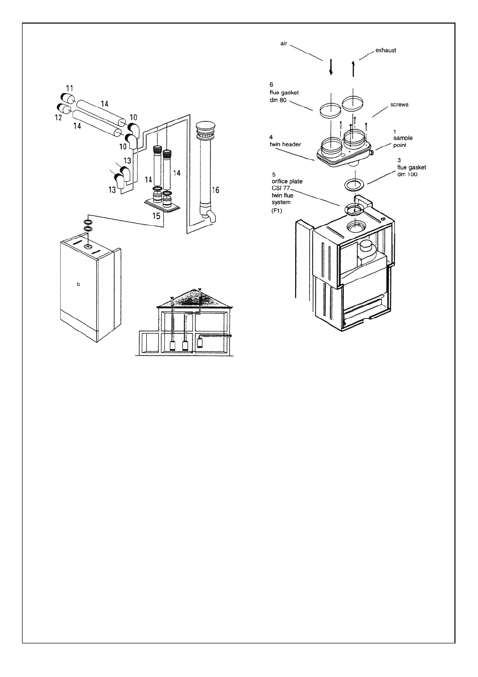
SECTION 10 INSTALLATION INSTRUCTION FOR
TWIN FLUE PIPE (ECCENTRIC FLUE DUCT SYSTEM).
10 - air intake bend 90°
10 - fl ue exhaust bend 90°
11 - air inlet terminal
12 - fl ue exhaust terminal
13- 45° air intake bend duct
13 - 45° fl ue exhaust bend
14 - fl ue exhaust duct
14 - air intake duct
15 - two-way fl ue gas header
16 - vertical eccentric fl ue exhaust duct
10.1 IMPORTANT.
These instructions must be read in
conjunction with the installation and
servicing
instructions.
As with all fl ues the kits must be installed
taking due account of the current issue of BS
5440 parts 1 & 2 and timber frame housing
REF
DM2.
Also note that the requirements will vary
depending upon the kit being installed.
Guidance is provided but unless otherwise
stated, always comply with the
recommendations of the relevant codes of
practice.
10.2
TWIN FLUE INSTRUCTIONS.
This part of the installation manual covers the
installation
and
fi xing instructions of the twin
fl ue eccentric fl ue duct systems only.
When ordering twin fl ue it must be stated for
CSI 85 (T) - 780 series range.
Typical installation procedures are illustrated
by
drawings.
IMPORTANT
Correct F1 orifi ce must be fi tted.
Supplied with the CSI twin fl ue header is a
F1 orifi ce plate along with supplementary
depression seal.
Before fi xing the twin fl ue system the existing
orifi ce plate must be replaced with F1 also
ensuring supplementary seal has been fi tted.
Remove the 13 screws securing the
depression front panel item 2 fi gure 39 to
expose front edge of depression chamber
(Twin fl ue instructions fi gure 1 adjacent) Using
adhesive sponge supplied with CSI twin fl ue
header, carefully attach to depression
chamber so as to create a softer seal.
Taking care not to damage the new seal,
carefully re-fi t the depression chamber front
cover in reverse order.
Take out the 4 temporarily fi tted securing
screws, lifting out the gasket and orifi ce plate
disconnecting it from the venturi tube.
Discard this orifi ce plate and re-fi t the F1 ori-
fi ce plate ensuring that the venturi tube has
been re-fi tted, making sure this is securely
located into the locating peg.
Fig. 61
Fig. 62