REMKO CMF-120-1P User Manual
Page 23
Electrical connection -
indoor module
The following instructions describe
the electrical connection of the
CMF and CMT Series indoor
module. Shown here is the
connection for the CMF Series.
Differences for connecting the
CMT Series are presented as they
arise.
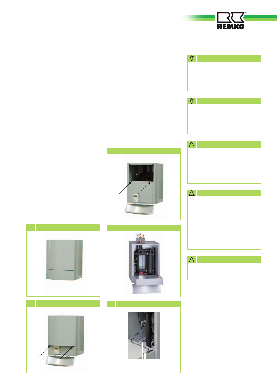
1. Fold down or remove the lower
housing-cover (Fig. 1).
2. Loosen the two screws that
secure the front of the housing
and move it upward (Fig. 2).
3. Loosen the two screws that
secure the control-box cover,
and lower it. Now, the cover
can be removed (Fig. 3) and
the control box
be lowered for inserting the
electric cables. (Fig. 4).
4. Thread the power cable - as
well as the control cable
between the indoor- and
outdoor modules and the cables
for external devices and sensors
- though the cable openings
into the indoor module (Fig. 5).
Note that the cable openings
in the CMT series are located
above rather than below.
Attach cables in accordance
with the connection schematic
and/or the circuit diagram in
the control box.
NOTE
The number of lines and the
sensors is dependent on the
configuration of the heating
system and the components.
NOTE
1 Remove the lower housing-cover
2 Loosen the screws
3 Loosen the screws
4
Lower the control box
Cable passage
5 Insert the cables
At the site, avoid adding cable
inlets.
!
CAUTION
Make sure to use enough cable
when installing the indoor
module so that the control box
can be fully lowered for future
maintenance.
!
CAUTION
Ensure correct polarity when
connecting the electrical leads,
especially the control cable.
!
CAUTION
23