Remko cmf / cmt, Circuit diagram (continued) – REMKO CMF-120-1P User Manual
Page 42
Advertising
REMKO CMF / CMT
Circuit diagram (continued)
Cir
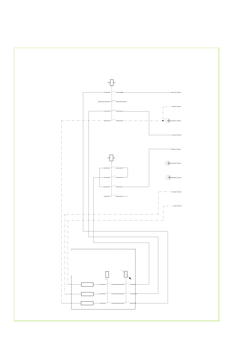
cuit diagram WP05
(CMF/CMT120/160-1P)
3 kW switch
Power supply for electric booster
-heating
3x230V/1~/50Hz
6 kW switch
Electrical
booster heat
3 x 3 kW
42
Advertising
This manual is related to the following products: