Hydraulic connection – REMKO CMF 320 Duo User Manual
Page 17
Hydraulic connection
■
We recommend installing
a buffer storage unit as
a hydraulic switch for
hydraulically isolation of the
heating circuit.
■
Make a pipe-network
calculation before installing the
heat pump. After installing the
heat pump, it is necessary to
perform a hydraulic balancing
of the heating circuit.
■
Protect floor heating systems
against excessively high inlet
temperatures.
■
Do not reduce pipe diameters
for the supply and return
connections to the heat pump
before connecting a buffer
storage-unit.
■
Plan for air bleed valves and
drain-off taps at appropriate
places.
■
Flush the the system's entire
pipe network before connecting
the heat pump.
■
One or, where necessary,
several expansion tanks must
be designed for the entire
hydraulic system.
■
The system pressure of the
entire pipe network is to be
matched to the hydraulic
system and must be checked
when the heat pump is turned
off. Also update the static-
pressure form supplied with the
heat pump.
■
As delivered, the safety
assembly consists of a
manometer, air bleeder and
safety valve. It is to be mounted
to the pipe connection provided
on the indoor module.
■
The heat pump requires a
constant, minimum standing-
water volume of 100 litres to
guarantee power for defrosting
and to assure a minimum
running time. Buffer storage
unit
■
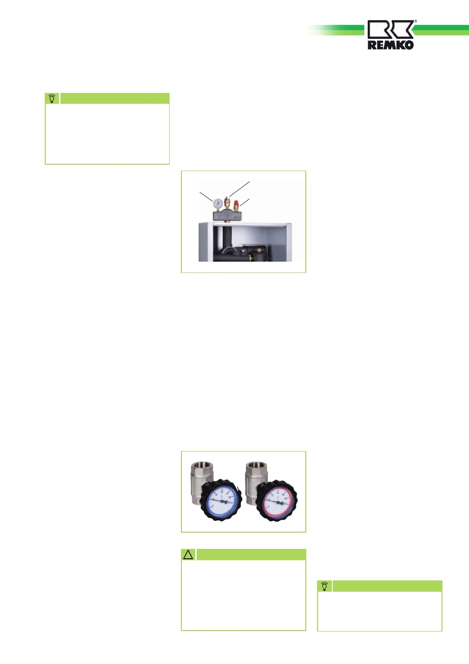
The stop cocks supplied are to
be positioned directly at the
connections for the heat pump
for the heater circuit inlet and
return lines.
The shut-off valves each contain
a thermometer.
■
Install the dirt traps delivered
with the unit outside the heat
pump in the return line. Ensure
that the dirt trap remains
accessible for inspection.
■
Be sure to position one gate
valve upstream and another
downstream of the dirt traps.
This ensures that the dirt traps
can be checked at any time
without loosing water.
■
The dirt traps must be checked
during every service of the
system.
■
Additionally, a hand-operated
bleeder is installed on the heat
pump for additional bleeding.
■
All visible metallic surfaces must
be additionally insulated.
■
Cooling mode via the heating
circuit requires a completely
vapour diffusion tight insulation
along the entire length of the
pipework.
■
All outgoing heating circuits,
including the connections
for water heating, are to be
secured against circulating
water by means of check
valves.
■
Before being placed in service,
the system must be thoroughly
flushed. Conduct a seal test and
perform a thorough bleeding
of both the indoor module and
the entire system - repeatedly,
if necessary.
A separate interpretation of
nominal flow rate must be
made for every system (see
attachment: Technical Data).
NOTE
Actual schemas for hydraulic
integration can be found on
the internet at www.remko.de
NOTE
Safety valve
Automatic bleeder
Manometer
Indoor unit
Turning the thermometer
heads serves to close or open
the stop valves! The dial be
brought into the desired posi-
tion.
!
CAUTION
17