Electrical connection - outdoor module, Caution – REMKO CMF 320 Duo User Manual
Page 21
Electrical connection -
outdoor module
■
The side wall of the the unit is to
be removed by means of loosening
the screws in order to connect the
mains supply (see "Installation of
the Outdoor Module").
Screws
Screw
■
Electrical protection for
the system is implemented
in accordance with the
information in the technical
data (see appendix). Observe
the required conductor cross-
sections!
■
All cables must be connected
with the correct polarity and
strain relief.
■
Follow the connection
schematic and the circuit
diagram.
■
Connect the four-wire control
cable to terminals S1, S2, S3
and the earth terminal.
■
When connecting the control
cable, make sure that polarity is
correct.
L3
N
S1
S2
S3
N
S1
S2
S3
PE
PE
Anschluss Innenmodul
Anschluss Außenmodul
Netzzuleitung
400V/3~N/50Hz
L2
L1
L3
L2
L1
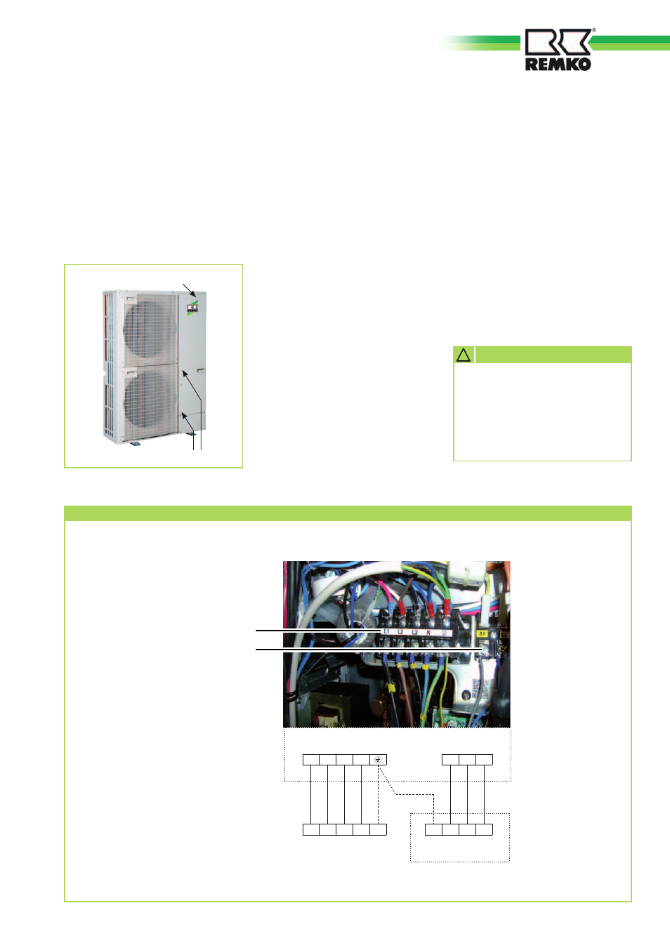
Connection terminals - outdoor module CMF 320
Mains connection
400V/3~/50Hz
Control cable
Outdoor-module connection
Indoor-module connection
Mains cable
400V/3~/50Hz
Make sure to connect the
outdoor module's neutral
connector properly, otherwise
the varistors on the line-filter
circuit board will be destroyed.
!
CAUTION
■
If the outdoor module is
installed on a roof, it and the
supporting structure must be
earthed separately. (Connection
to a lightning rod or a concrete-
footing earth electrode)
21