7 commissioning (specialist), 1 general information, 2 filling the primary circuit – REMKO EFS 35 User Manual
Page 15: Commissioning (specialist), General information, Ba c, Filling the primary circuit
7
Commissioning (specialist)
7.1
General Information
NOTE:
Open the valves in the pipes and the fresh water
station slowly, in order to prevent pressure
shocks.
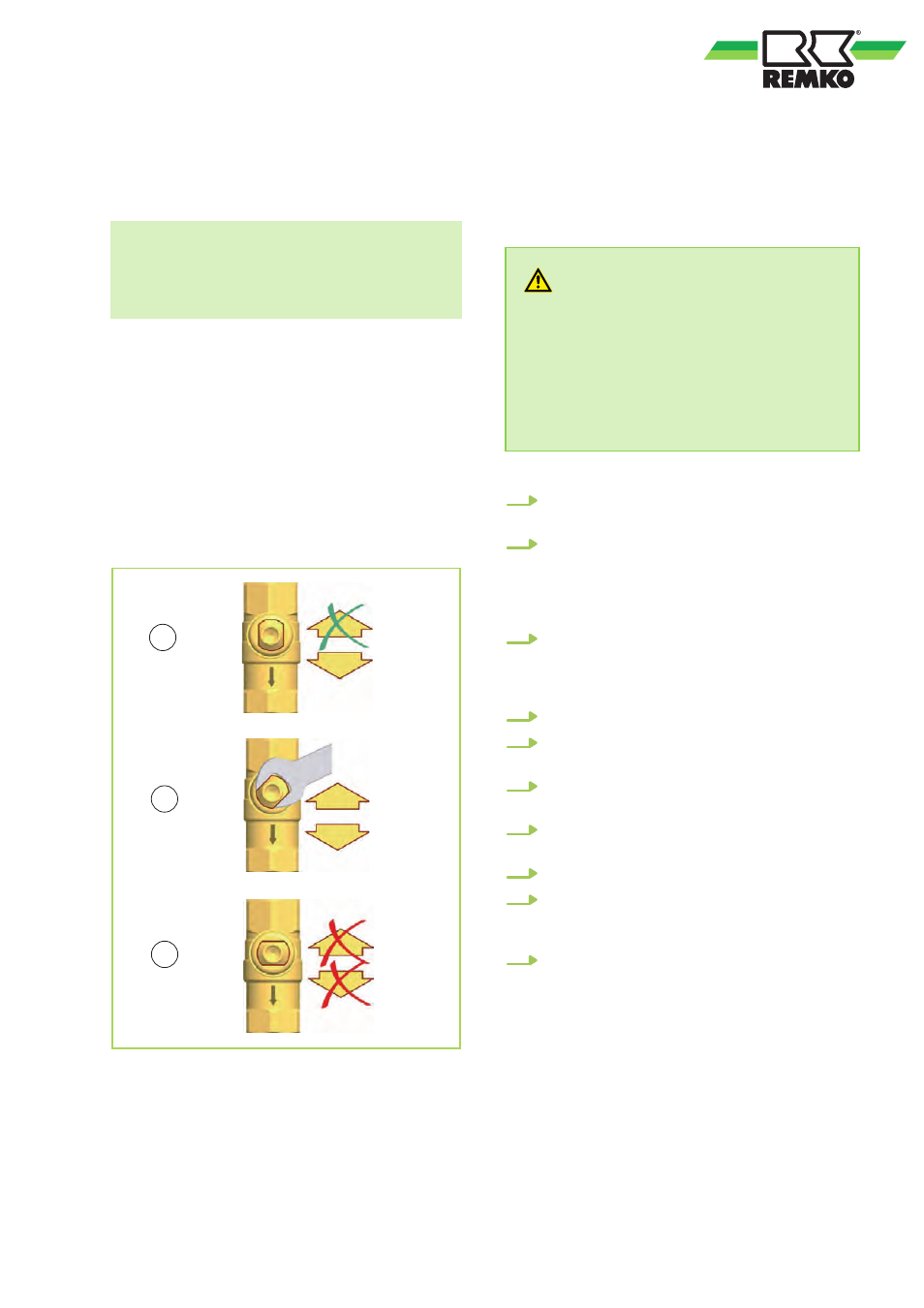
Function of the gravity brake
The primary circuit is equipped with a gravity brake
in the ball valve, in order to prevent undesired
gravity circulation.
The gravity brake must be opened to bleed and
clean the system. To do this, turn the ball valve to
the 45° position. The gravity brake is out of opera-
tion.
All ball valves and valves must be opened com-
pletely (0°) in order to operate the system.
B
A
C
0°
45°
90°
14
Fig. 6: Setting the gravity brake
A: 0° position - Gravity brake in Operation, only
flowing in flow direction.
B: 45° position - Gravity brake out of Operation,
flowing in both directions.
C: 90° position - Ball valve closed, no flow.
7.2
Filling the primary circuit
If the storage tank is (partially) filled
CAUTION!
Danger of scalding due to hot water!
The system is under pressure. By opening the
ball valve for filling/drainage, water of up to 90
°C can leak out of the ball valve for filling/
drainage, which may cause bodily injury.
–
Open the ball valve for filling/drainage
slowly and from a safe distance.
1.
Open the ball valve (F) by turning it to the 0°
position.
2.
Fill the storage tank using the filling valves
provided by the customer until you reach an
operating pressure of 1.5 bar*. Use the
heating water in accordance with VDI 2035 /
ÖNorm H5195-1.
3.
Connect a hose to the ball valve for filling/
drainage (B). Carefully actuate the ball valve
for filling/drainage (B) and allow the air to
bleed out.
4.
Connect the ball valve for filling/drainage (B).
5.
Close the ball valve (F) by turning it to the
90° position.
6.
Open the ball valve (G) slowly by turning it to
the 45° position.
7.
Carefully actuate the ball valve for filling/
drainage (B) and allow the air to bleed out.
8.
Connect the ball valve for filling/drainage (B).
9.
After bleeding, check the operating pressure
of the storage tank and increase it if neces-
sary.
10.
Open the ball valves (F) and (G) completely
by turning them to the 0° position.
1.5 bar in the primary circuit = recommended
minimum value.
The system pressures that depend on the design
and the components of the heating system are
also crucial for the pressure
15