4 maximum dispensing medium flow rate, Maximum dispensing medium flow rate – REMKO EFS 35 User Manual
Page 17
7.4
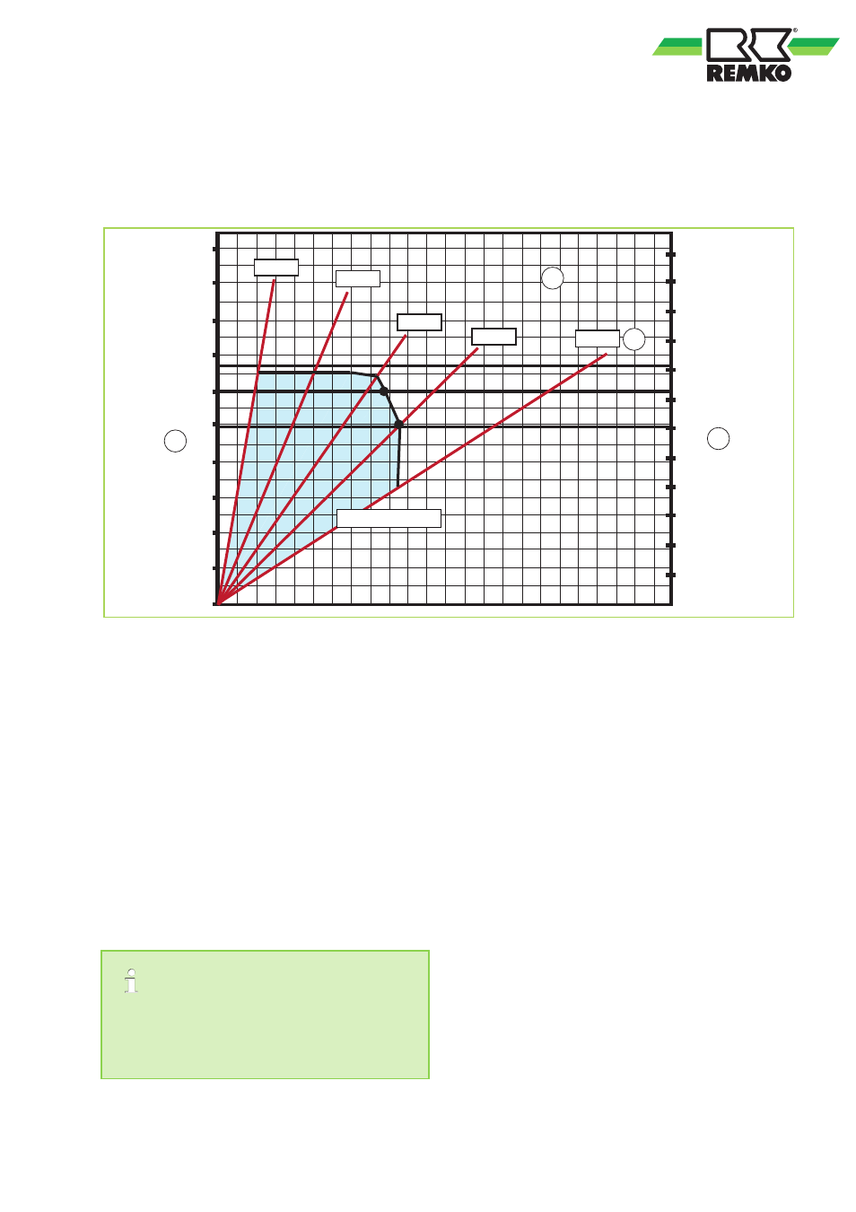
Maximum dispensing medium flow rate
The following diagram shows the maximum dispensing medium flow rate depending on the storage tank
temperature; this assumes a pre-set hot water temperature of 45 °C at the dispensing connection. The inte-
grated controller prevents the temperature from decreasing as long as the maximum medium flow rate is not
exceeded.
B
[kW]
0
10
20
30
40
50
60
A
[l/min]
0
20
40
60
80
100
120
140
70 °C
90 °C
80 °C
65 °C
80
90
100
70
160
180
200
220
240
1
2
50 °C
Friwa EFS 35
Fig. 9: Maximum dispensing medium flow rate
A:
Dispensing medium flow rate [l/min]
B:
Power [kW]
1:
Hot water temperature: 45 °C
2:
Buffer storage temperature
Boundary conditions:
Cold water temperature: 10 °C,
Maximum pressure loss on the domestic water
side of the fresh water station: 1000 mbar
The following examples explain the relationships
between the individual variables of the hot water
temperature, the dispensing medium flow rate and
the buffer tank temperature, and show how these
affect the transmission capacity of the fresh water
station.
The hot water temperature that is set in the
Smart Control controller (S 08 probe) is the ref-
erence temperature for the buffer tank. Factory
setting: 45 °C.
Example 1
Hot water temperature at the dispensing connec-
tion: 45 °C
Temperature in the buffer tank: 60 °C
ð
Maximum dispensing medium flow rate: 50 l/
min, transmission capacity: 121 kW
Example 2
Hot water temperature at the dispensing connec-
tion: 45 °C
Maximum dispensing medium flow rate: 60 l/min
ð
Temperature in the buffer tank: ~70 °C,
transmission capacity: 145 kW
17