Feeder interface cables, Stand-alone operation – Rena XPS-ProFeed Shuttle User Manual
Page 10
INSTALLATION
-
4
-
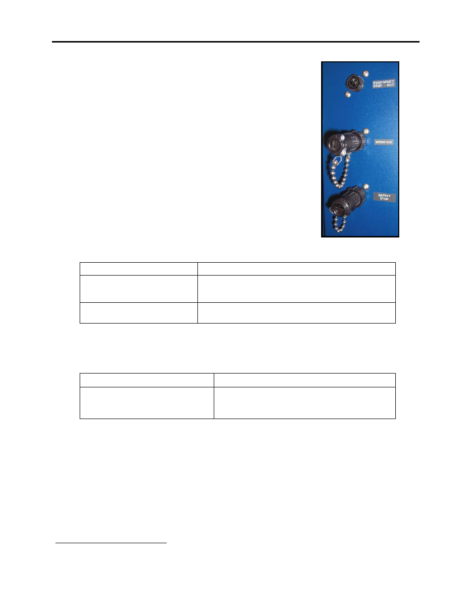
2. The jumper plug for the feeder “interface” connection, located at
the rear of the feeder, should be removed and the appropriate
feeder interface cable (see info below) should be attached between
the feeder’s “INTERFACE” connector and the printer’s “feeder”
connector.
3. Connected the optional Emergency Stop Cable between the
“Emergency Stop Out” connection on the feeder and the “Safety
Stop” connection on the XPS-ProMail Base.
4. Connected the optional Safety Stop Cable between the “Safety
Stop” connection on the feeder and the “Emergency Stop Out”
connection on the XPS-ProMail Base; or install the jumper plug
provided, to the appropriate connection on the back of the feeder.
Feeder Interface Cables
Standard Feeder Interface Cables:
Application
Feeder Interface Cable
XPS-ProFeed Shuttle Feeder
XPS-ProMail 3.0/4.0 Printer
25E-500-205
(included with XPS-ProMail Base)
(25E-500-201 may be substituted)
XPS-ProFeed Shuttle Feeder
XPS-ProTab 4.0
*33E-500-192 rev A
(included with XPS-ProTab 4.0)
* “33E-500-192” is an old cable that can only be used with the EasyFeed 120,
“33E-500-192 rev A”, can be used with the EasyFeed 120 or XPS-ProFeed Shuttle.
Feeder Interface Cables for System Configurations:
The following feeder interface cables can be purchased for system configurations:
System
Feeder Interface Cable
XPS-ProFeed Shuttle Feeder
XPS-ProTab 4.0
XPS-ProMail 3.0/4.0 Printer
25E-500-201 or
25E-500-205 & 25E-500-210
Stand-alone Operation
To run the feeder in “stand-alone” mode (no control cables connected to other machines); the
two Jumper Plugs, shown in the image above, must be attached to the back of the feeder.
1
Cable connects Tabber and Printer to Feeder, so each can control the Start/Stop function of the feeder.