Section 2 – installation, Power requirements, Attaching to the xps-promail base – Rena XPS-ProFeed Shuttle User Manual
Page 9: Warning
INSTALLATION
-
3
-
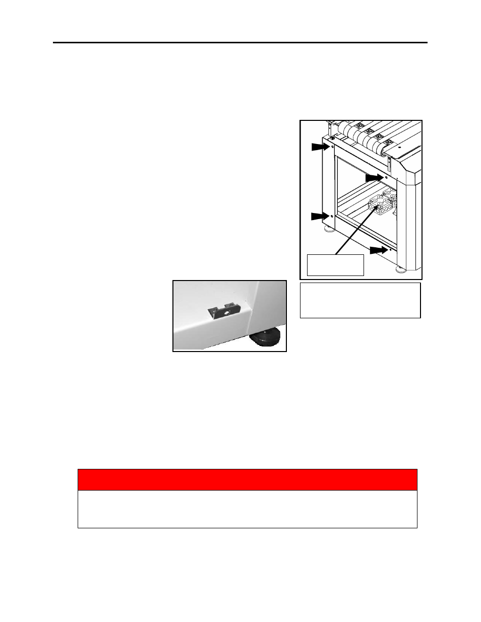
XPS-ProMail Base
Showing AC Outlets and XPS-
ProFeed Shuttle attachment points.
20A, 125V
Switched Outlet
Section 2 – Installation
Power Requirements
The XPS-ProFeed Shuttle requires a 3 wire, 20 Amp, 125 Volt, single phase, AC outlet.
The 20 Amp, 125V plug, on the feeder power cord, prevents
you from connecting this feeder to a standard outlet.
A 20 Amp, 125V outlet is provided, inside the XPS-ProMail
Base. This outlet is switched on/off with base power.
Attaching to the XPS-ProMail Base
Note: If you plan to use an XPS-ProTab 4.0, in between the
XPS-ProFeed shuttle and XPS-ProMail Base, please disregard
this attachment information.
Make sure that XPS-ProMail Base is disconnected from the
power source.
Remove the covers from the feeder and main base cabinets.
Attach the mounting
bracket to the base of the
Shuttle Feeder as shown.
supplied with the Shuttle
Feeder. This bracket will
provide a fourth mounting
hole, which will be used to
attach the feeder to the XPS-
ProMail Base.
There are four (4) threaded holes on the XPS-ProMail base. To attach the Shuttle Feeder to
the base align the four (4) holes in the feeder cabinet with the four threaded holes in the base
and attach with the Cap Head Screw and Washer supplied.
Connecting Power and Interface Controls to the XPS-ProMail Base
1. The power cord from the feeder should be routed through the oval hole, provided in the
base unit. The power cord should be plugged into the receptacle marked Switchable,
located inside the XPS-ProMail Base.
WARNING
THE FEEDER POWER CORD SHOULD BE PLUGGED INTO THE RECEPTACLE
BOX MARKED SWITCHABLE SO THAT WHEN THE STOP BUTTON ON THE
BASE UNIT IS ACTIVATED THE FEEDER WILL ALSO STOP.