0) air for combustion, 1) direct outside air for combustion – Space Ray RSTP Series User Manual
Page 24
Form 43206000
Sept 2011
-23-
B.
B.
B.
B.
INDIRECT VENTING (UNVENTED HE
INDIRECT VENTING (UNVENTED HE
INDIRECT VENTING (UNVENTED HE
INDIRECT VENTING (UNVENTED HEATERS)
ATERS)
ATERS)
ATERS) — This heater requires ventilation in the building to dilute the
products of combustion and provide fresh air for efficient combustion. Where unvented heaters are used,
gravity or mechanical means shall be provided to supply and exhaust at least 4 CFM per 1,000 Btu/hr input
of installed heaters. Exhaust vents must be located at the highest point above and in the vicinity of the
heaters, and the inlet vents must be located below the level of the heaters. An exhaust hood must be used
as described in Section 10.0). NOTE:
NOTE:
NOTE:
NOTE: Exhaust Hoods are supplied as Accessory items.
Exhaust
Hood
15.0)
AIR FOR COMBUSTION
If indoor combustion air is to be supplied for a tightly enclosed area, one square inch of free area opening shall
be provided below the heater for each 1,000 Btu/hr of heater input. Adequate clearances around the air inlet
screen must be maintained at all times. In larger open areas of buildings, infiltration normally is adequate to
provide air for combustion.
15.1)
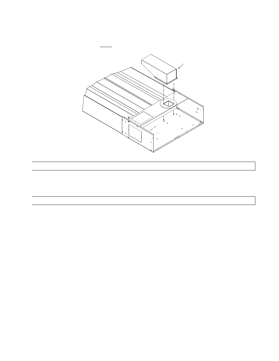
DIRECT OUTSIDE AIR FOR COMBUSTION
Outside combustion air should be supplied directly to the heater when the building is subject to negative
pressure, or when contaminants or high humidity are present in the building air. These contaminants include
paints, solvents, corrosive vapors or any other foreign particles that may cause damage to the heater or result in
poor combustion.
Outside combustion air can be brought directly to the heater by a 6” diameter duct less than 50 ft. long or
equivalent (see table in Section 14.0). This is attached to the 6” diameter starting collar. The starting collar is
fitted to the top of the control box cabinet after first removing and discarding the perforated cover
after first removing and discarding the perforated cover
after first removing and discarding the perforated cover
after first removing and discarding the perforated cover and installing
and installing
and installing
and installing
an adapter plate (Part #42783000)
an adapter plate (Part #42783000)
an adapter plate (Part #42783000)
an adapter plate (Part #42783000). Alternately the combustion air can be brought from the side, after replacing
the solid cover panel on the side with an adapter plate, and replacing the perforated cover panel on the top with
the solid cover panel from the side. An approved vent cap must be placed directly on the end of the outside
combustion air inlet pipe. The combustion air inlet should be not less than 3 ft. (0.9m), either vertically or
horizontally, from the flue vent termination. The air intake terminal must be located not less than 1 ft. (30cm)
above grade. It is good installation practice to supply combustion air from the same pressure zone as the vent
outlet. Avoid bringing combustion air to the heater from an attic space. There is no guarantee that adequate
combustion air will be supplied.
In colder climates, where necessary, insulate the outside combustion air duct. Avoid locating the outside
combustion air duct directly above the control box. Provide a capped cleanout T as necessary. In high humidity
applications, the control box should be sealed with silicone sealer.
In multiple heater applications
multiple heater applications
multiple heater applications
multiple heater applications, the combustion air intake may be ducted individually or common ducted in the
same configuration as shown for venting in Section 14.0). For combustion air intake duct sizing, please refer to
the Vent Sizing Table
Vent Sizing Table
Vent Sizing Table
Vent Sizing Table and use the diameter indicated, based on the number of heaters per duct.