0) control component location – Space Ray RSTP Series User Manual
Page 28
Advertising
Form 43206000
Sept 2011
-27-
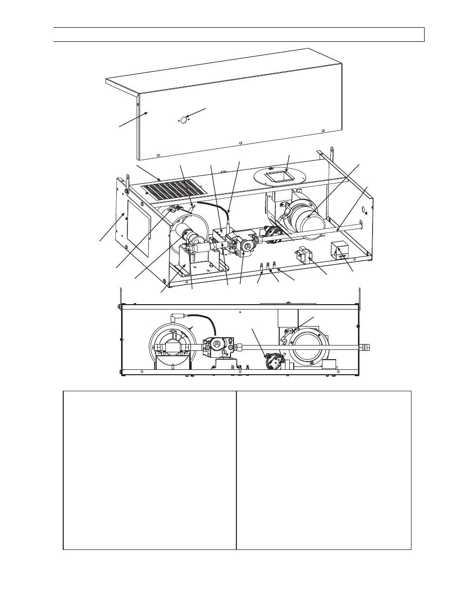
18.0)
CONTROL COMPONENT LOCATION
1
Cabinet Assembly
2
Air Inlet Plate
3
Access Panel
4
Sight Glass
5
Flame Sensor
6
Ignition Module
7
Ignition Cable (partially shown)
8
Flue Outlet
9
Draft Inducer
10
Manifold Tubing
11
Terminal Block and Shield
12
Transformer (120/24 VAC)
13
Monitoring Light, Green
14
Monitoring Light, Red
15
Monitoring Light, Amber
16
Gas Valve
17
Nipple
18
Nipple and Plug
19
Entrance Cone & Support Assembly
20
Main Burner
21
Spark Electrode
22
Air Switch
23
Air Sensing Probe
10
1
2
4
13
14
15
3
18
16
5
6
7
8
9
11
12
19
20
21
22
23
17
Advertising