2) removing main burner and gas valve, 3) air switch pressure check – Space Ray RSTP Series User Manual
Page 34
Form 43206000
Sept 2011
-33-
21.2)
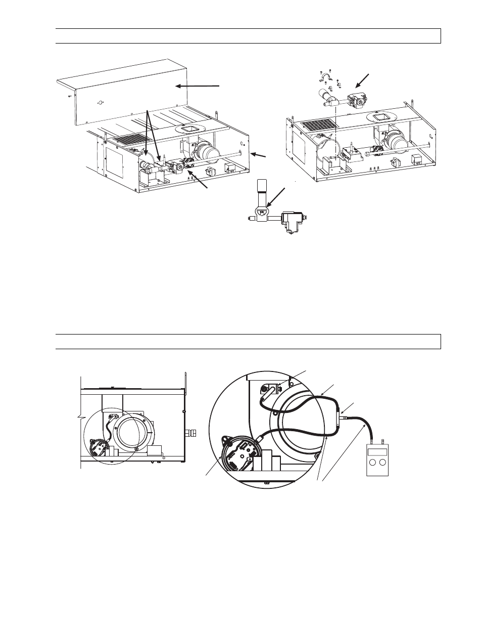
REMOVING MAIN BURNER AND GAS VALVE
3
4
5
6
1
2
1.
Disconnect electrical supply and gas connection from control box.
2.
Remove the access panel and disconnect the wires from gas valve.
3.
Disconnect the nut and sleeve from the gas valve compression fitting.
4.
Remove screws, large burner clamp and both small manifold clamps from the manifold support.
5.
Lift complete burner and gas valve assembly from the heater.
6.
Check the orifice. If the gas valve is to be replaced, the pipe joint compounds must be resistant to the action
of liquefied petroleum gases.
21.3)
AIR SWITCH PRESSURE CHECK
Temporary 1/4 ID
Silicone / plastic
tubing for pressure
test.
Air Switch
Plastic Vacuum
Air Tube
0.16 WC
+
-
Air sensing
tube bracket
Connector Tee
Digital or Inclined
Water Manometer
scale 0-2w.c.
a.
Open access panel.
b.
Add tubing to connect the air switch with the connector tee and the existing tubing.
c.
Connect plastic tubing of a digital or inclined water manometer with a 0-2” scale onto the connector tees.
d.
Turn heater on and wait until blower motor is activated.
e.
Observe air pressure from manometer. This should be higher than the set point 0.16” w.c. for correct
operation.
All pressures are with the heater in operation for at least 15 minutes.
All pressures are with the heater in operation for at least 15 minutes.
All pressures are with the heater in operation for at least 15 minutes.
All pressures are with the heater in operation for at least 15 minutes.