System control – Sundance SMT395Q User Manual
Page 16
Version 1.0.7
Page 16 of 31
SMT395Q User Manual
System Control
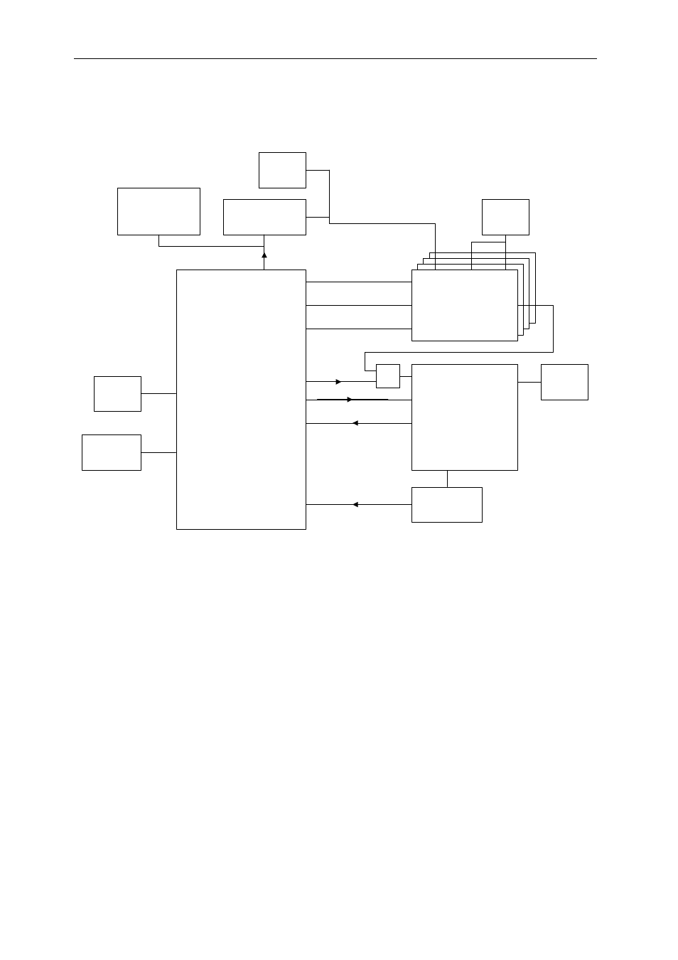
Control of the system is provided via a TI MPS430 micro-controller. This is run at 8MHz, and
provides several dozen user-defined pins. These are connected as shown below.
DSP
DSP
DSP
FPGA
(XC2VP70)
VirtexII-Pro, FF1704
996 I/O Pins
1.5V
MPS430
Micro-Controller
DSP
OSC
120MHz
DS1085L
programmable
oscillator
OSC
50MHz
OSC
8MHz
RS232
connector
MAX1617
Temperature
sensor
OSC
125MHz
LVPECL
Fit one only
Core
clk
EMIFB
clk
EMIFA
clk
CLKMODE
BEA17-14
RESET
(with pull-down)
PROGRAM
Data and strobes
Int
DXN/P
3-wire serial
Tx/Rx
SCL,SDA
DS1805
Programmable
pot for DSP core
PSU
OR
Starting at the top, the MPS430 is connected via an I
2
C serial bus to a DS1805
programmable potentiometer. This pot is inserted into the DC-DC converter feedback, and
thus can be used to adjust the DC-DC’s output. The output is pre-set to 1.25V on power-up.
The minimum value is 0.9V, and the maximum is above the Texas Instruments
recommended voltage. Exceeding the absolute maximum voltage will cause damage to the
DSPs.
Also connected to the I
2
C bus is a DS1085L programmable oscillator. This enables a wide
range of frequencies to be generated for the DSP core clock input. This is a build option,
normally a fixed oscillator is provided.
The four DSPs share two oscillators for the EMIF bus speed. EMIF_B is run at 50MHz,
whereas EMIF_A is run at 120MHz. The MPS430 is able to hold the DSPs in a reset state,
and then it can change the CLKMODE (PLL multiplier), and EMIF bus speed options (via
pins BEA17-14).
The assertion of the FPGA’s PROGRAM pin (clears the configuration) is under control of
both the MPS430 and the DSP (connected to BCE2). The MPS430 will assert this pin if it
detects that the FPGA’s core temperature has risen to an unacceptable level.