Sundance SMT395Q User Manual
Page 17
Advertising
Version 1.0.7
Page 17 of 31
SMT395Q User Manual
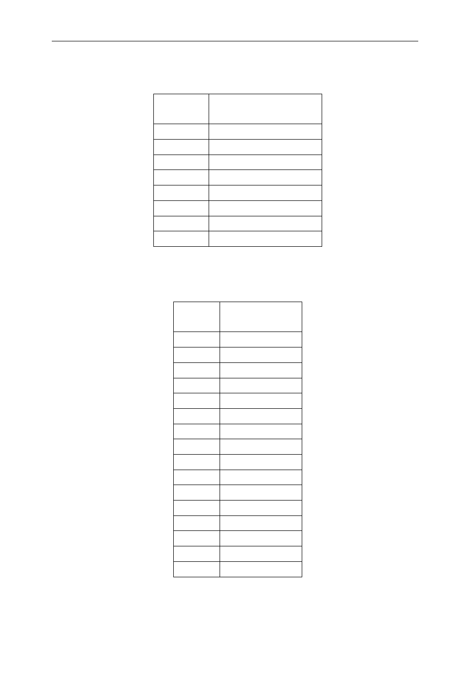
There is an 8-wire interface between the MPS430 and the FPGA. The signal functionality is
shown here;
Signal Function
F0 Data
0
F1 Data
1
F2 Data
2
F3 Data
3
F4 RD
strobe
F5 WR
strobe
F6 Reset
F7 Int
Power and temperature measurements are passed over this bus and into the FPGA. The
following table shows the values and register locations:
Location Value
00-03
Gen. Purpose 1
04-07
Gen. Purpose 2
08-0B DSP_A
3.3V
0C-0F DSP_A
core
10-13 DSP_B
3.3V
14-17 DSP_B
core
18-1B DSP_C
3.3V
1C-1F DSP_C
core
20-23 DSP_D
3.3V
24-27 DSP_D
core
28-2B DDR
high
2C-2F DDR
low
30-33 FPGA
high
34-37 FPGA
low
38-3B
DSP core PSU
3C-3F FPGA
temp
Advertising