Board operating parameters – Sundance SMT395Q User Manual
Page 19
Version 1.0.7
Page 19 of 31
SMT395Q User Manual
Board Operating Parameters
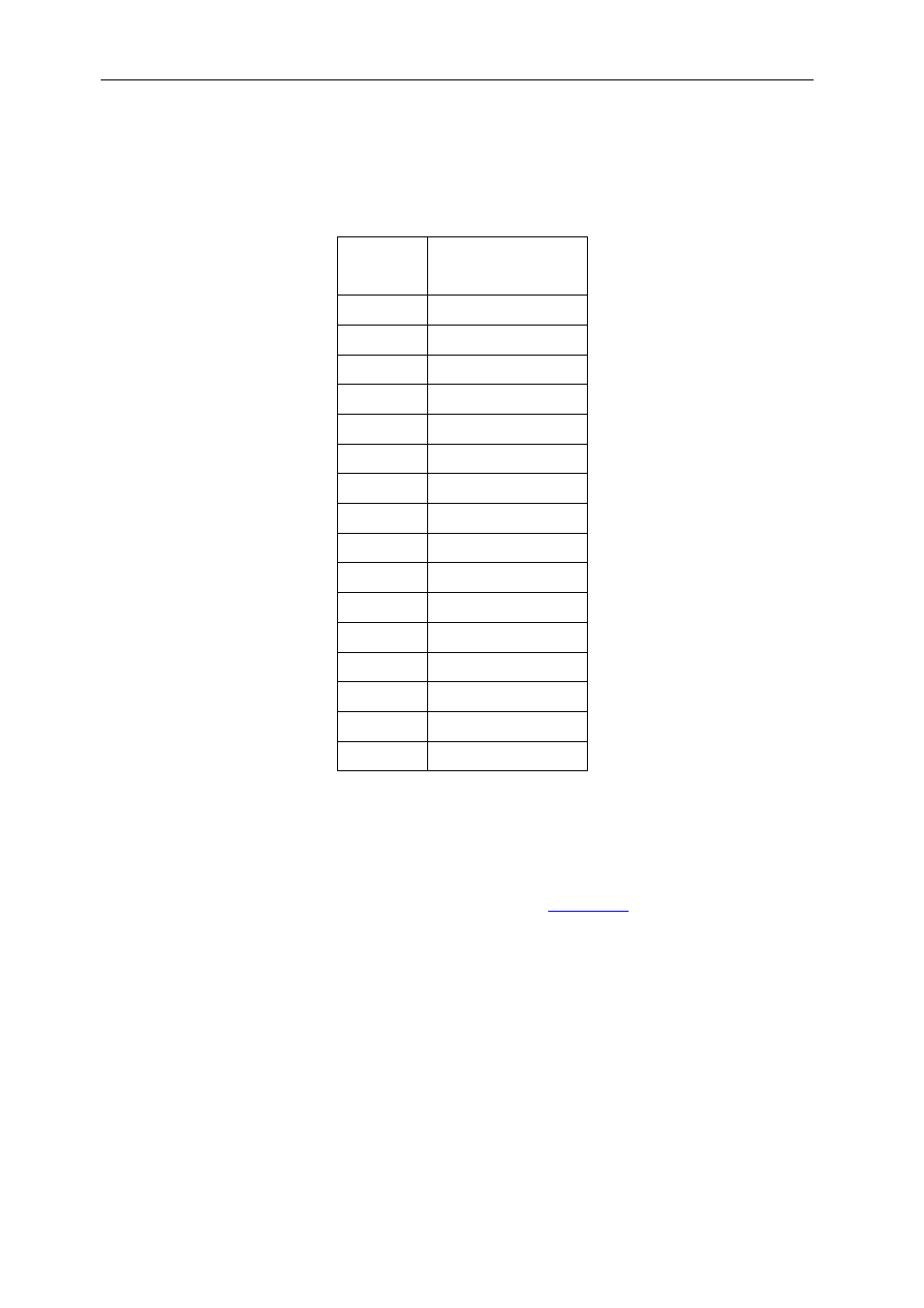
Various board operating parameters can be set using the following registers:
Location Value
(hex)
00-03
~Gen. Purpose 1
04-07
~Gen. Purpose 2
08-0B Rsvd
0C-0F Rsvd
10-13 OS
14-17 DAC
18-1B MUX
1C-1F Rsvd
20-23 Core
vltg
24-27 ~Core
vltg
28-2B
Core PLL mult.
2C-2F EMIF_A
speed
30-33 EMIF_B
speed
34-37 Rsvd
38-3B Rsvd
3C-3F Rsvd
Once the register values have been written (all registers must contain valid data), then the
BOARD_PARAM_UPDATE register is written to. This will indicate to the MSP430 that new
parameters are available to read, and that it should alter the necessary hardware controls.
The OS, DAC and MUX values are written directly into the DS1085L registers
(programmable clock generator). Reference to the Maxi
.
The Core vltg value is written directly into the DS1805E device (programmable pot controlling
the DSP core voltage). A value of 126 (dec) will produce a core voltage of 1.2V. The power-
on value provides a core voltage of 0.9V (until the micro-controller finishes its power-on
sequence, when the voltage will be set to 1.25V).
Values greater than 126 will produce a
voltage in excess of the TI recommended absolute maximum, and should therefore be
avoided.
The ~Core vltg value is the complement of Core vltg. If ~Core vltg is not the
complement of Core vltg, then no core voltage setting will take place.
The maximum core voltage value is stored in non-volatile memory and cannot be
erased.