Power connector, Jumpers/links, Jp3 – prog sel – Sundance SMT395Q User Manual
Page 26: Jp1 – fpga jtag, Power connector jumpers/links, Jp3 – prog sel jp1 – fpga jtag
Version 1.0.7
Page 26 of 31
SMT395Q User Manual
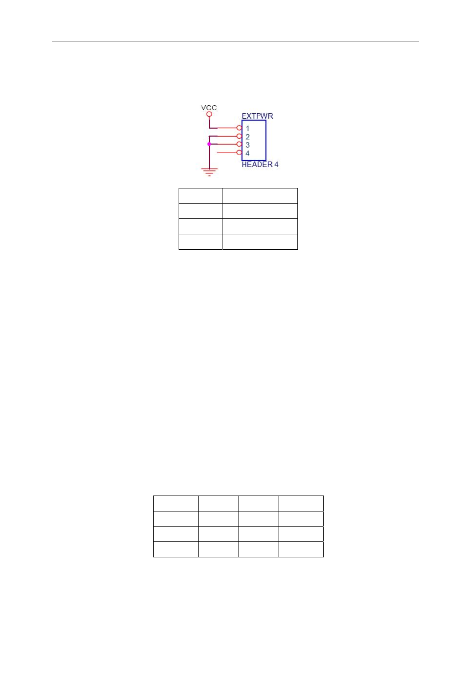
Power Connector
The external power connector EXTPWR is described below:
Pin_1
+5V VCC
Pin_2
GND
Pin_3
GND
Pin_4
Not connected
Jumpers/Links
JP3 – Prog Sel.
The position of this jumper determines the way the FPGA’s PROG pin is controlled.
With the jumper to the right (towards pin 1, factory default), the PROG pin can be asserted
by either DSP_A or the micro-controller (over temperature condition).
With the jumper to the left, the PROG pin will be asserted low continuously. This can be
useful if a non-functioning bitstream has been loaded which could potentially prevent re-
programming of either the FPGA or flash memory.
With the jumper removed, the PROG pin cannot be asserted, and thus the FPGA can be
configured only once (until power cycled). This is strongly advised against as the over-
temperature control is also bypassed.
[Note that future versions of this module will allow the over-temperature condition to assert
PROG regardless of the jumper setting]
JP1 – FPGA JTAG
This table shows the pin-out and organisation of the FPGA’s JTAG header.
Signal Pin Pin Signal
GND 6 3 TCK
TDO 5 2 TMS
TDI 4 1 Vcc
Connect this header to a Xilinx Parallel Cable IV, for directly loading custom bitstream.