Super Systems HP2000 With 9100 Controller User Manual
Page 2
Electrical Connections
Remove the screw cover on the electrical enclosure box on the side of the main box. Route the
green “S” Type thermocouple wire and the black and white sensor wire (for connection to the
probe) through the access hole at the bottom of the box. Route the power wire (110VAC ONLY)
in through the same hole, and connect it to the terminal block according to the diagram below.
Tighten the wire clamp at the electrical access hole and replace the screw cover to the electrical
enclosure box.
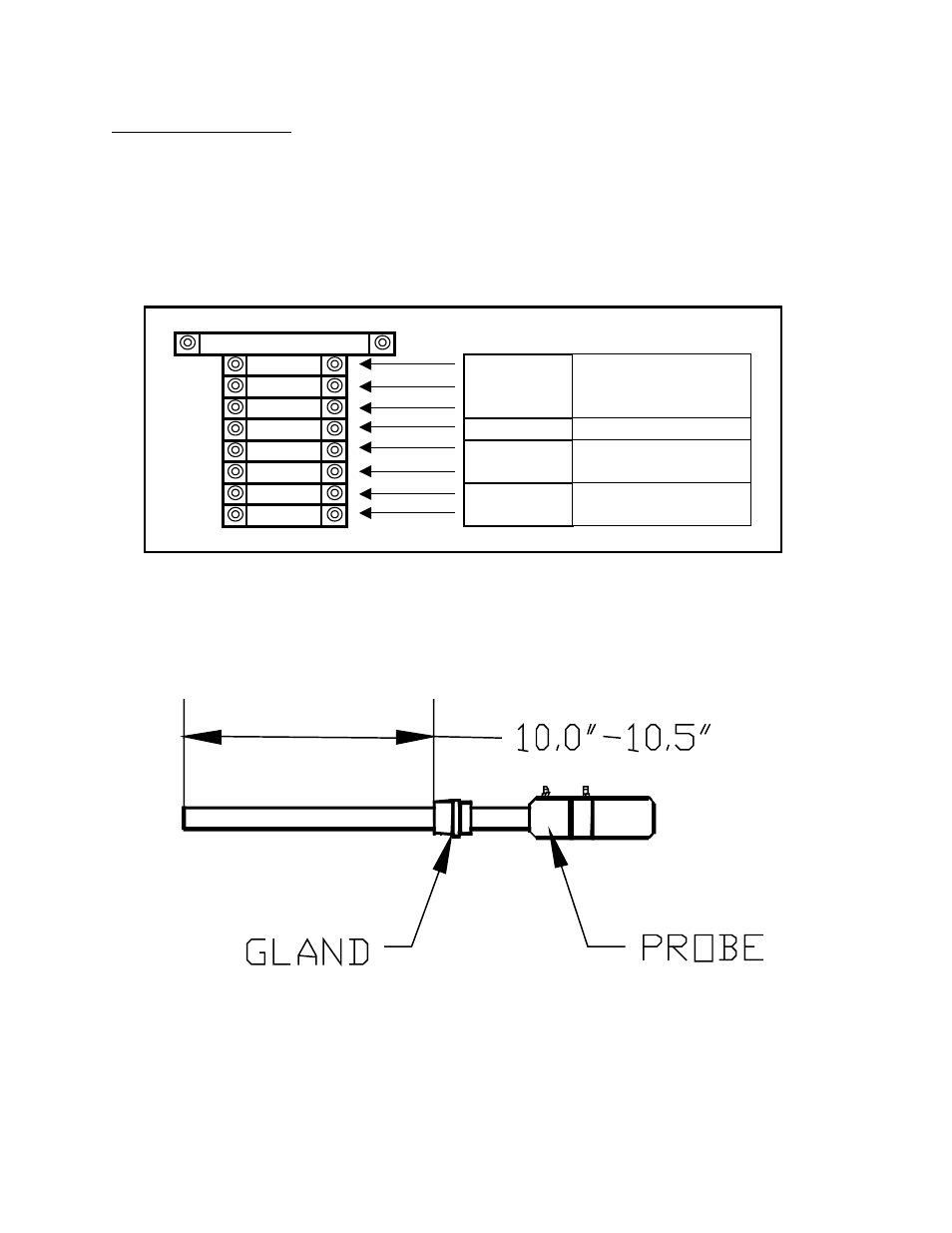
Insert the probe into the coupling at the base of the large box. It is important that the probe is
inserted at the correct depth to allow proper heating and prevent damage to the ceramic
well inside the unit. There should be between 10.0” and 10.5” between the bottom of the
adjustable 1” NPT gland and the end of the probe (see sketch below).
2.0 AMP
1000
Line
1002
Neutral
GND
Ground
SPARE
N/A
1141
Positive
1151
Negative
1331
Positive
1341
Negative
110VAC
1 PHASE
50-60 HZ
Host Communications
(RS 485)
UNUSED
4-20mA OUTPUT
(0-25% O2)