Installation – Verilink PRISM 3060-10 (34-00252.4) Product Manual User Manual
Page 14
6
I
NSTALLATION
✦
The PRISM 3060-10/DSU MP reference manual
✦
AC power supply cord
The TXPORT 3010 -400 is shipped from the factory with the following standard
equipment:
✦
3010 -400 reference manual (p.n. 34-00252)
✦
two 120-pin D-subminiature to six DB-25 adapter cables (p.n. 7-3010-266-010).
For specific applications, additional cables and adapters may be required for the
installation and operation of the unit. The interface requirements of any application
may be met by using the appropriate cable. Standard cables and TXPORT ordering
numbers are listed in Ordering Numbers on page 66. Contact TXPORT for
assistance in cable selection.
Installation
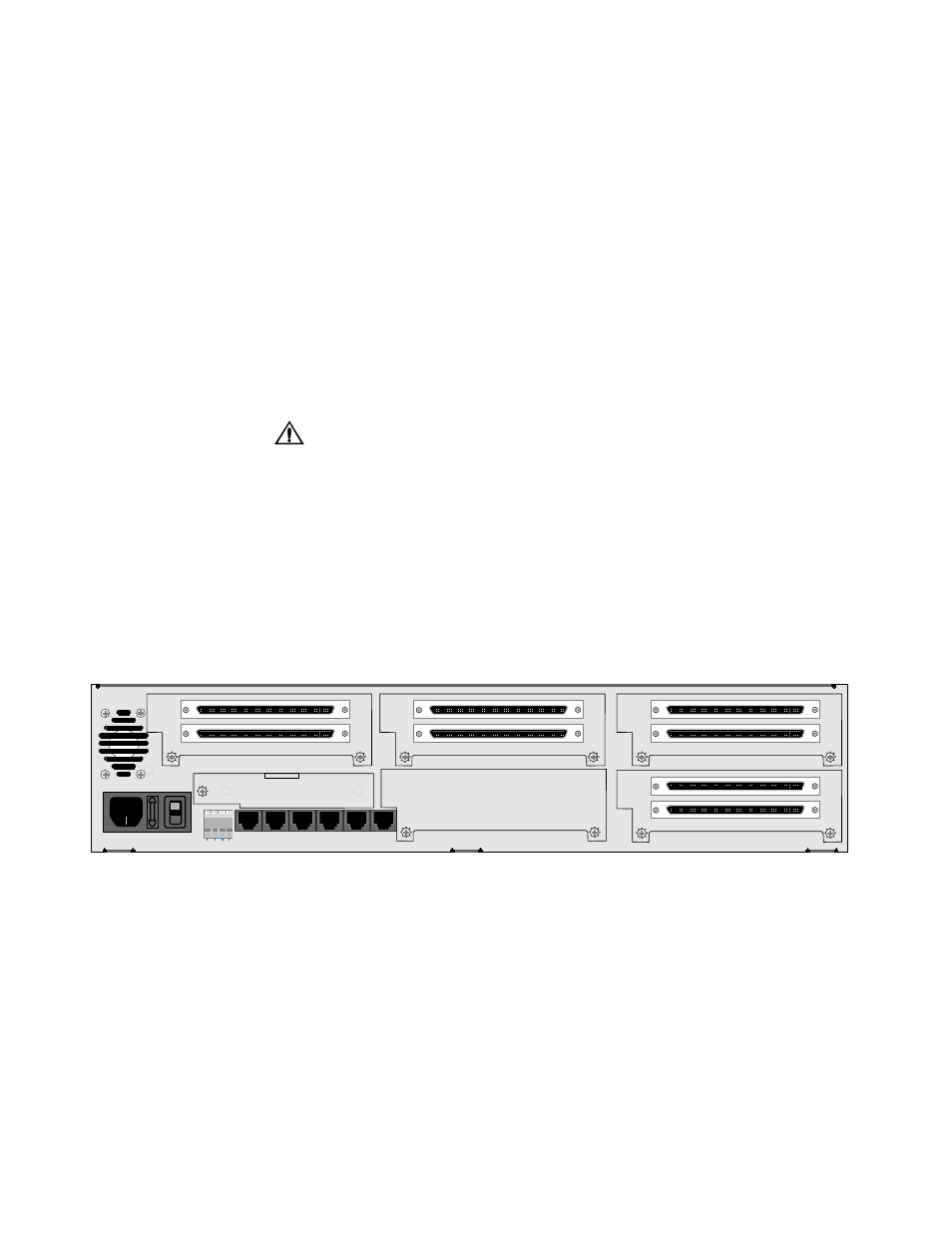
The 3010 -400 card fits into slots 3, 4, 5, or 6 of a 3060-10.
To prevent electric shock or damage to the unit, turn the rear panel power switch OFF
before removing or installing any option modules.
To add a module to an empty slot, power the unit off and remove the cover plate.
Carefully slide the new card along the guides with the unit oriented as shown in
Figure 2-2. Push the board in until the faceplate rests against the rear panel. Ensure
that it seats without displacing the flexcable connector. Then, insert the screws.
If resistance is encountered when inserting the card, remove the card and verify
that there are no obstructions its path. Also check for bent or damaged pins in the
connectors on either the module or the chassis.
Do not press on the front panel LCD when inserting the option card.
ALARM RELAY
GRN NO C NC
SLOT 1
NMS
IN
NMS
OUT
SUPV
STATION
CLOCK
T1
DTE
T1
NET
O
I
REPLACE WITH SAME
FUSE TYPE/RATING
110/220VAC 50-60HZ .6A/.3A
FUSE 1.0A 250V SLO-BLOW
A SLOT 4 B
A SLOT 5 B
A SLOT 6 B
A SLOT 2 B
A SLOT 3 B
1-3
4-6
1-3
4-6
1-3
4-6
1-3
4-6
Figure 2-1 Rear Panel of the 3060-10 Equipped with Four DSU MPs