2 connections – Westermo ED-20 User Manual
Page 9
Advertising
9
6609-2222
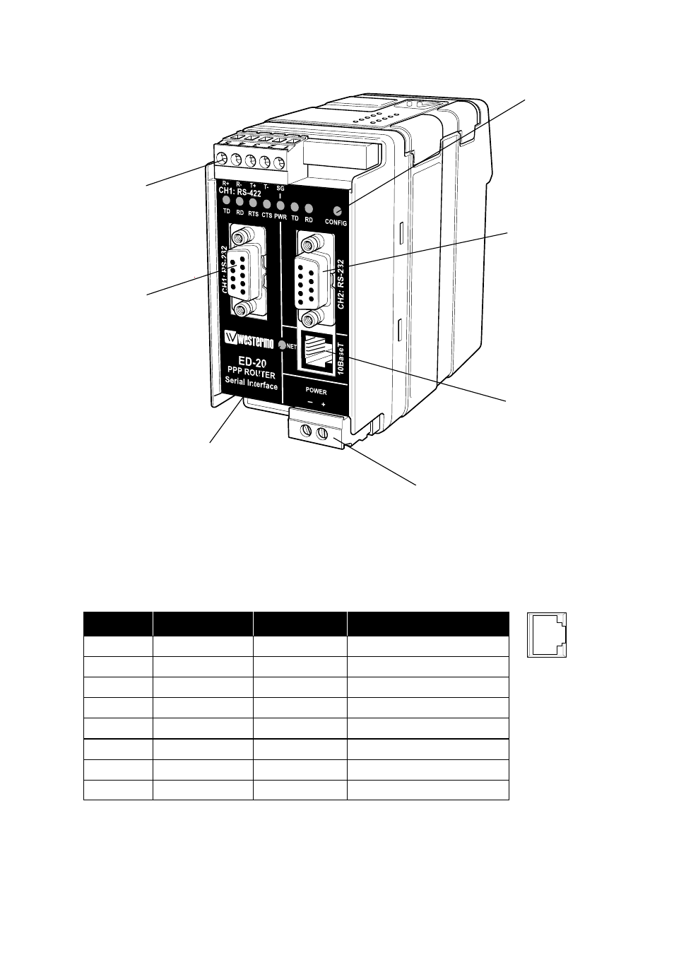
6.2 Connections
Power
LED indicators
LED indicators
Channel 1:
RS-232 connection
Channel 1:
RS-422 connection
Channel 2:
RS-232 connection
Ethernet 10Base-T
connection
8
7
6
5
4
3
2
1
Ethernet 10Base-T Connection (RJ-45 connector)
Media Dependent Interface (MDI)
Contact
Signal Name
Direction**
Description
1TD+
Out
Transmitted Data
2
TD–
Out
Transmitted Data
3
RD+
In
Received Data
4
NC
5
NC
6
RD–
In
Received Data
7
NC
8
NC
**
Direction relative ED-20
NC
Not connected
CAT 5 cable is recomended.
Unshielded (UTP) or shielded (STP) cables might be used.
Advertising