7. status menu status menu – ATL Telecom AM64/512 User Manual
Page 11
a
telecom
telecom
User Guide
User Guide
High Speed Modems
High Speed Modems
11
7.
7. Status Menu
Status Menu
The status menu will display information indicating the overall status of the modem. The Status Menu
display has two levels ; The top level indicating the general status, the second level (down arrow key)
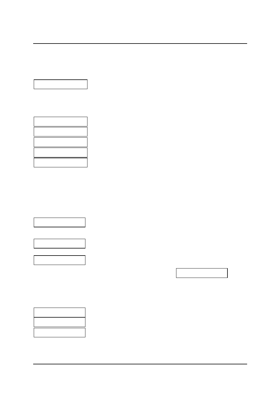
giving further details. The highest priority status message is;
This indicates that a loop is active within this unit, or a loop has been applied by this unit.
It is possible to transmit the Control signals from one unit to another or to configure the units so that they
are permanently switched on. The LCD indicates the status of the modem at any given time as;
Indicates Modems not in Synchronisation
Indicates Modems in Synchronisation but, Control Signals not on either end
Both Modems Control Signals on and in Synchronisation
Remote Modem Control Signals on
Local Modem Control Signals on
If Control Signals are being used then the state of the I or 109, C or 105 lines are ;
Both ends on
-
Data Transfer,
Local end on
-
Send Data,
Remote end on -
Receive Data,
Neither end on -
LTU Ready,
Lost Sync
-
LTU Not Ready.
This message set indicates that there is no synchronisation with the remote
modem, this could be due to a disconnected line, configuration error or other
fault.
CRC error indicates that there are errors detected in the incoming line data
(only visible when In Service Test is running)
The BBM is operating with no alarms present.
A modem fitted with a G.703 Interface has extra alarm messages
This alarm may be active on its own or in conjunction with the transmission system LOS. In order to
accommodate this, the LOS alarm in the status menu has been extended. There are four possible messages
displayed;
The transmission system has lost sync.
The G.703 interface cannot extract clock from received signals.
The transmission system has lost sync and the G.703 cannot extract the clock
from received signals.
There are no displays showing interface circuits since the G.703 interface has no control lines.
S> Loop Active
S> Loop Active
S> LTU Not Ready
S> LTU Not Ready
S> LTU Ready
S> LTU Ready
S> Data Transfer
S> Data Transfer
S> No Sync
S> No Sync
S> CRC errors
S> CRC errors
S> Receive Data
S> Receive Data
S> Send Data
S> Send Data
S> No Alarm
S> No Alarm
S> G.703 sync fail
S> G.703 sync fail
S> LOS / CD Fail
S> LOS / CD Fail
S> CD Fail
S> CD Fail
S> LOS
S> LOS