Interface modules – ATL Telecom AM64/512 User Manual
Page 27
a
telecom
User Guide
High Speed Modems
Interface Modules
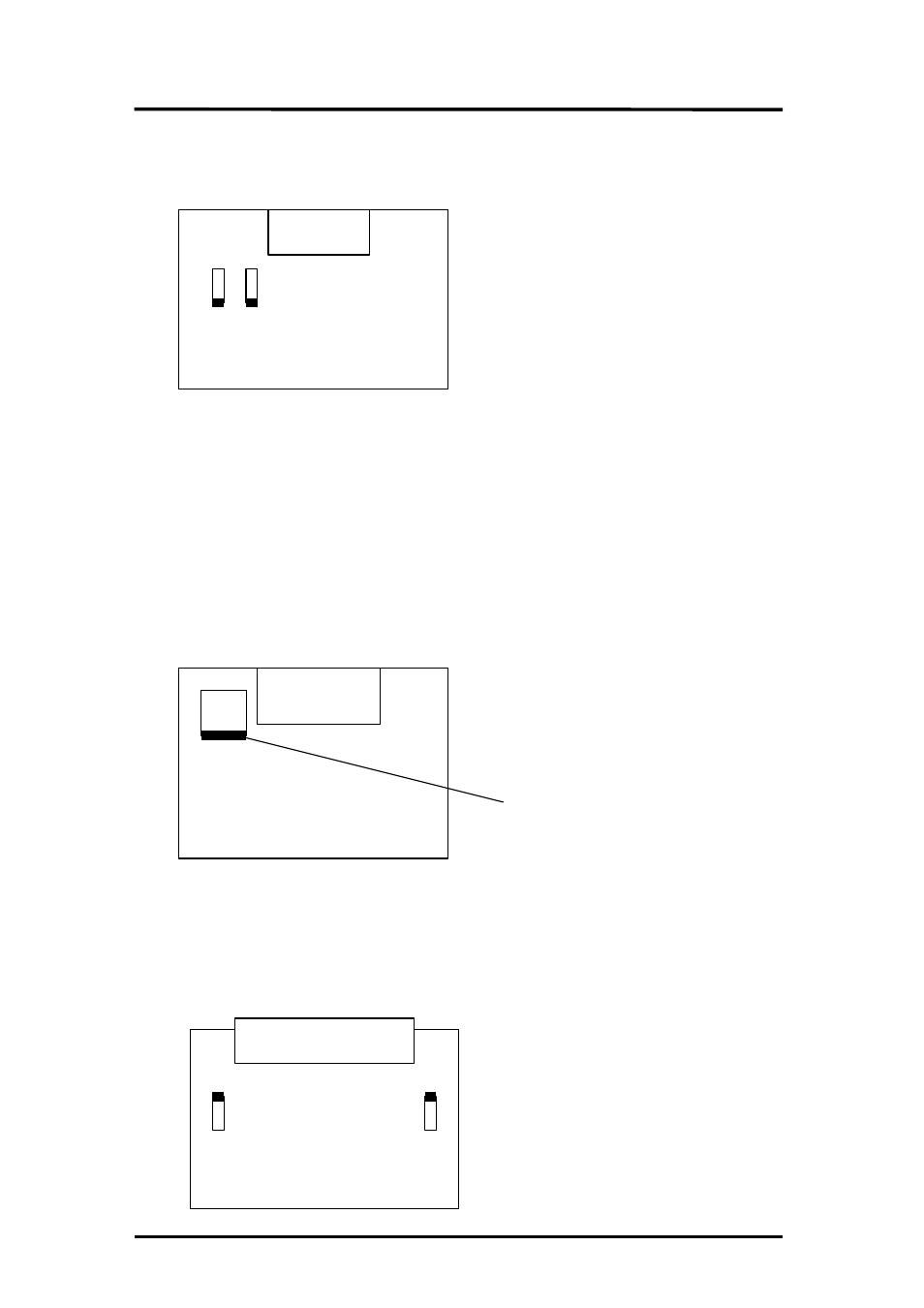
X.21 Interface Module :
J1 - T - Circuit
J2 - Circuit S Ext Termination.
J1 - X.21 T (Transmit data) Circuit Termination – This link connects a 120 ohm load resistor
across the T circuit position 1-3. This helps maintain signal rise times and minimises reflections at
rates greater than 9.6 kbps over long lines. At lower rates and over short lines the termination
resistor may be omitted, (link set position 1-2).
J2 – X.21 SEXT (External Signal Element Timing) Circuit Termination – This link connects a 120
ohm load resistor across the SEXT circuit in position 1-3. This helps maintain signal rise times and
minimises reflections at rates greater than 9.6 kbps over long lines. At lower rates and over short
lines the termination resistor may be omitted, (link set position 1-2).
V.35 Interface Module :
3 3
1
2
J1
Removable link shown joining pins 1-2,
to reverse connection of A and B wires
to Circuit 113 move link to position 1-3.
J1 – V35 Circuit 113 (External Signal Element Timing) Input Polarity Selection – This aspect of the
V35 interface may be implemented differently by different manufacturers. This link allows the
authorised personnel to swap the polarity of the A and B wires of this differential input circuit.
The factory default setting for this position 1-2.
V.36 Interface Module :
J1 - T - Circuit
J2 - Circuit S Ext Termination.
A-6
J2 J1
SK1
V35 MRAC
CONNECTOR
J1
J1 J2
SK1