Appendix b – internal link settings – ATL Telecom AM64/512 User Manual
Page 24
Advertising
a
telecom
User Guide
High Speed Modems
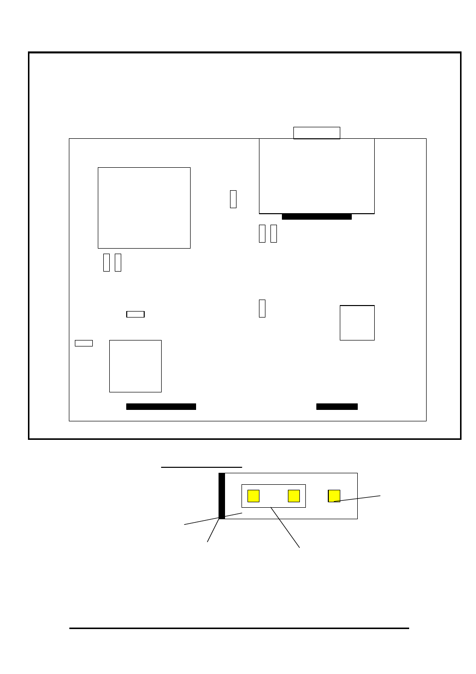
APPENDIX B – Internal Link Settings
The following diagram shows the location of the internal BBM links :
Jumper Detail
Pin Numbering Format
2 1 3
2 1 3
Gold Pins
PCB Silk Print
Bar marked on PCB Removable Link
All of the links have 3 pins, the bar end indicating pin 2.
A-4
LK200
PL4
LK2 LK3
LK203 LK201
LK102
LK1
LK101
PL7
PL8
IC100
IC1
Interface Module
Mains
Transformer
Advertising