ATL Telecom AM64/512 User Manual
Page 22
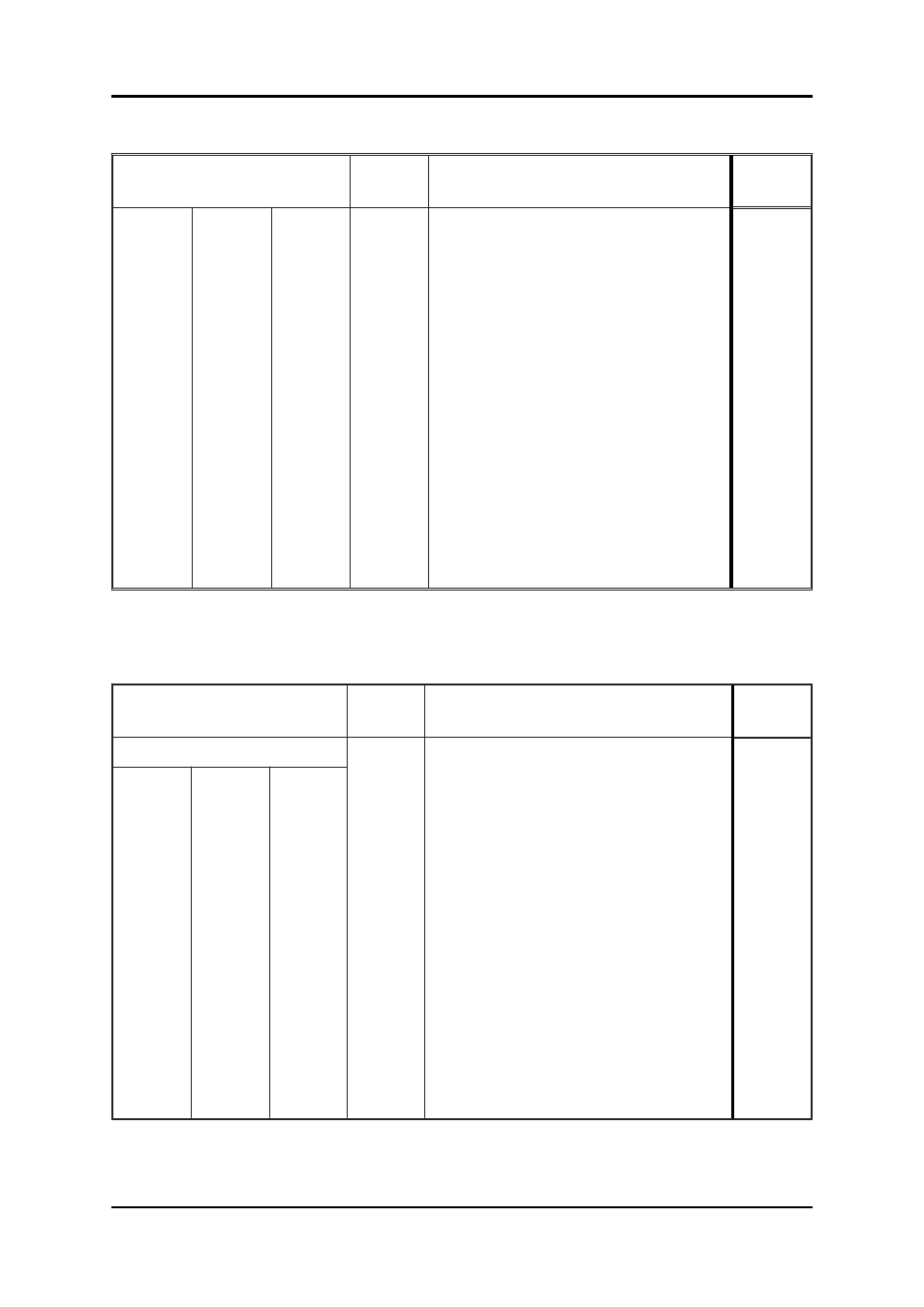
V.35 (MRAC ) Con nec tor Pin Al lo ca tion
Pin
Type SITS
Unbal
A Wire
B wire
Cir cuit
De scrip tion
89/43
B
102
Com mon Re turn
Com mon
P
S
103
Trans mitted Data
Load
R
T
104
Re ceived Data
Generato
r
C
105
Re quest to Send
Load
D
106
Ready for Sending
Gen er a tor
E
107
Data Set Ready
Gen er a tor
F
109
Data Chan nel Re ceived
Gen er a tor
U
W
113
Ex ter nal Trans mit ter Sig nal El e ment Tim ing
Load
Y
AA*
114
Trans mit ter Sig nal El e ment Tim ing
Gen er a tor
V
X
115
Re ceiver Sig nal El e ment Tim ing
Gen er a tor
N
140
Re mote Loopback
Load
L
141
Lo cal Loopback
Load
NN*
142
Test In di ca tor
Gen er a tor
Note that on some MRAC con nec tors pin `AA' is marked as `a' and pin `NN' is marked `m'.
37 Way D-type V.36 Con nec tor pin al lo ca tion
Pin
Type SITS
Unbal
A Wire
B wire
Cir cuit
De scrip tion
89/43
19, 20, 27, 29, 31
102
Com mon Re turn
Com mon
4
22
103
Trans mitted Data
Load
6
24
104
Re ceived Data
Gen er a tor
7
25
105*
Re quest to Send
Load
9
(9)
(27)
106*
Ready for Sending
Gen er a tor
11
(11)
(29)
107*
Data Set Ready
Gen er a tor
13
(13)
(31)
109*
Data Chan nel Re ceived
Gen er a tor
17
35
113
Ex ter nal Trans mit ter Sig nal El e ment Tim ing
Load
5
23
114
Trans mit ter Sig nal El e ment Tim ing
Gen er a tor
8
26
115
Re ceiver Sig nal El e ment Tim ing
Gen er a tor
14
140
Re mote Loopback
Load
10
141
Lo cal Loopback
Load
18
142
Test In di ca tor
Generator
* Stan dards in di cate that the con trol cir cuits 105, 106, 107, 109 may be im ple mented as bal anced cir cuits
(us ing both A and B wires) or un bal anced sin gle ended cir cuits. In the case of the con trol cir cuits the A wire is
to be used and the B wire is to be joined to GND (cir cuit 102) at the re ceiver end of the cir cuit.
A-2
a
telecom
User Guide
High Speed Mo dems