Configuration procedure, Figure 4 – H3C Technologies H3C S12500 Series Switches User Manual
Page 31
23
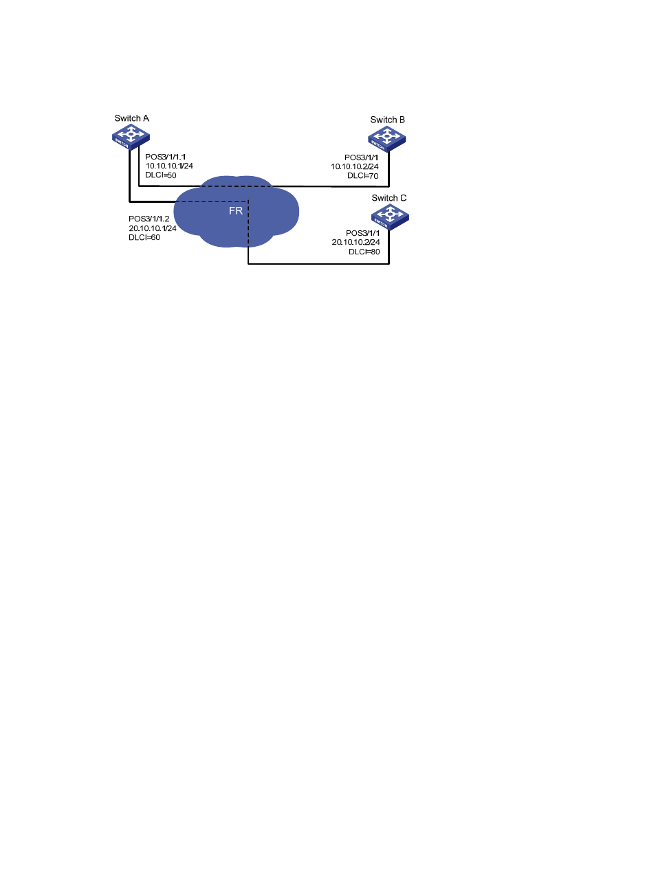
Switch A uses frame relay sub-interfaces to connect Switch B and Switch C in different network segments.
Figure 4 Network diagram
Configuration procedure
1.
Configure Switch A:
# Configure POS interface 3/1/1.
<SwitchA> system-view
[SwitchA] interface Pos 3/1/1
[SwitchA-Pos3/1/1] clock slave
# Configure frame relay encapsulation on the interface.
[SwitchA-Pos3/1/1] link-protocol fr
[SwitchA-Pos3/1/1] fr interface-type dte
[SwitchA-Pos3/1/1] quit
# Create sub-interface 1 on the interface.
[SwitchA] interface Pos 3/1/1.1
[SwitchA-Pos3/1/1.1] ip address 10.10.10.1 255.255.255.0
[SwitchA-Pos3/1/1.1] fr dlci 50
[SwitchA-Pos3/1/1.1] fr map ip 10.10.10.2 50
[SwitchA-Pos3/1/1.1] mtu 1500
[SwitchA-Pos3/1/1.1] quit
# Create sub-interface 2 on the interface.
[SwitchA] interface Pos 3/1/1.2
[SwitchA-Pos3/1/1.2] ip address 20.10.10.1 255.255.255.0
[SwitchA-Pos3/1/1.2] fr dlci 60
[SwitchA-Pos3/1/1.2] fr map ip 20.10.10.2 60
[SwitchA-Pos3/1/1.2] mtu 1500
[SwitchA-Pos3/1/1.2] quit
2.
Configure Switch B:
# Configure interface POS 3/1/1.
[SwitchB] interface Pos 3/1/1
[SwitchB-Pos3/1/1] clock slave
# Configure frame relay encapsulation on the interface.
[SwitchB-Pos3/1/1] link-protocol fr
[SwitchB-Pos3/1/1] fr interface-type dte
[SwitchB-Pos3/1/1] ip address 10.10.10.2 255.255.255.0