Vrrp with multiple vlans configuration example, Network requirements, Configuration procedure – H3C Technologies H3C WX3000E Series Wireless Switches User Manual
Page 36
28
Master IP : 202.38.160.2
The output shows that when VLAN-interface 3 on AC 1 is not available, the priority of AC 1 is
reduced to 80 and it becomes the backup. AC 2 becomes the master and packets sent from the
client to the host are forwarded by AC 2.
VRRP with multiple VLANs configuration example
Network requirements
•
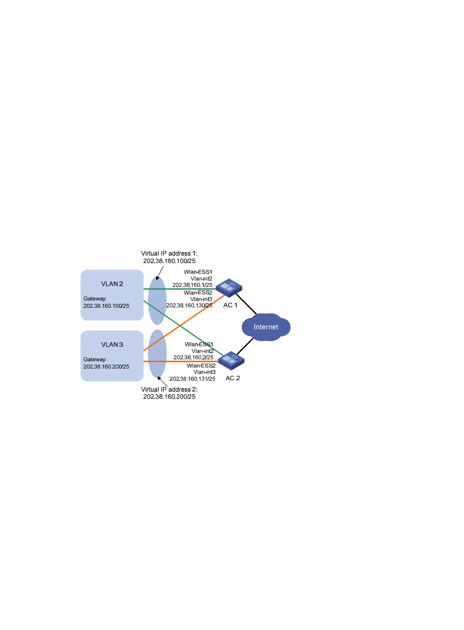
The hosts in VLAN 2 use 202.38.160.100/25 as their default gateway and the hosts in VLAN 3 use
202.38.160.200/25 as their default gateway.
•
AC 1 and AC 2 belong to both VRRP group 1 and VRRP group 2. The virtual IP address of VRRP
group 1 is 202.38.160.100/25, and that of VRRP group 2 is 202.38.160.200/25.
•
In VRRP group 1, AC 1 has a higher priority than AC 2. In VRRP group 2, AC 2 has a higher priority
than AC 1. In this case, hosts in VLAN 2 and VLAN 3 can communicate with external networks
through AC 1 and AC 2 respectively, and when AC 1 or AC 2 fails, the hosts can use the other
switch to communicate with external networks to avoid communication interruption.
Figure 12 Network diagram
Configuration procedure
1.
Perform basic configurations according to the topology requirements. (Details not shown.)
2.
Configure AC 1:
# Configure VLAN 2.
<AC1> system-view
[AC1] vlan 2
[AC1-vlan2] quit
[AC1] interface WLAN-ESS 1
[AC1-WLAN-ESS1] port link-type hybrid
[AC1-WLAN-ESS1] undo port hybrid vlan 1
[AC1-WLAN-ESS1] port hybrid vlan 2 untagged
[AC1-WLAN-ESS1] port hybrid pvid vlan 2
[AC1-WLAN-ESS1] quit
[AC1] interface vlan-interface 2