Rear view components, About the ft server – Grass Valley FT Server User Manual
Page 9
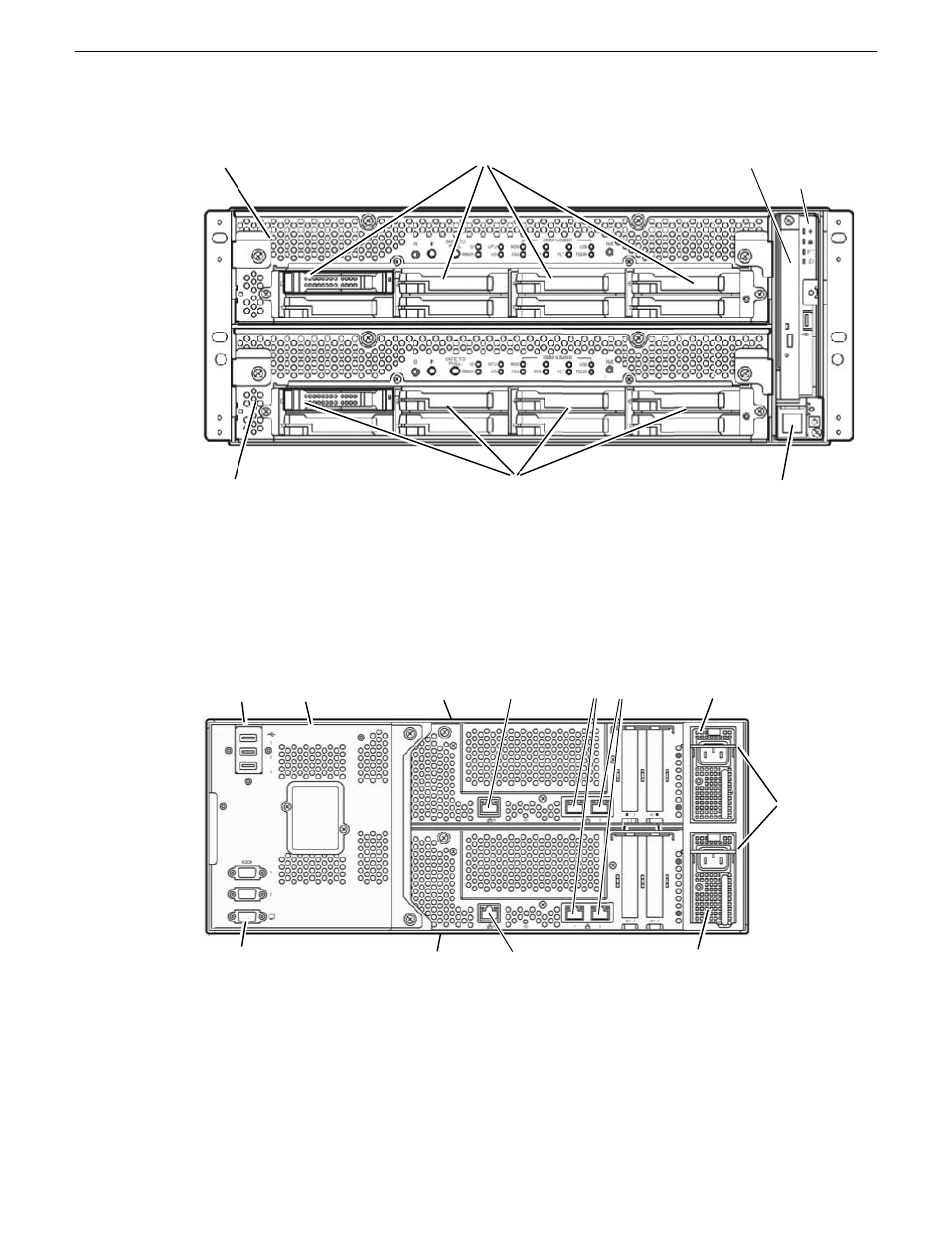
CPU/IO Module 1
Hard Drive Bays 0-7
Hard Drive Bays 0-7
Optical Disk Drive
On/Off switch
CPU/IO Module 1
LED Module
Related Topics
Front status LEDs (bezel removed)
on page 59
Rear view components
A rear view of the main components of the FT server is shown below.
CPU/IO module 0
power supply
CPU/IO module 1
power supply
Management
LAN for CPU/IO 1
Management
LAN for CPU/IO 0
Teamed
Duplex LANs
3 USB ports
VGA connector
CPU/IO
module 0
CPU/IO
module 1
Backplane
AC cord
stopper
bars
The system backplane connects to the left rear of both CPU/IO modules. It provides USB connectors
for mouse and keyboard control and serial connectors for maintenance when working with Customer
Service and a VGA connector for connecting to a monitor.
The CPU/IO modules each have a separate removable power supply. When an AC cord in installed
in the receptacles for each power supply, the AC cord stopper bars will be pushed up. In this position,
the CPU/IO modules cannot be removed until the AC cords are removed (no power to CPU/IO
modules).
20131220
FT Server Instruction Manual
9
About the FT Server