Cabling diagram, Step 2: networking setup – Grass Valley KMV-3901 Quick Start v.7.80 User Manual
Page 14
8
Setting Up Your KMV-3901/3911 Multiviewer
Networking Setup
10 When you are satisfied with the selected output resolution settings, press the Select
button on the front edge of the KMV-3901/3911 card to exit the control menu.
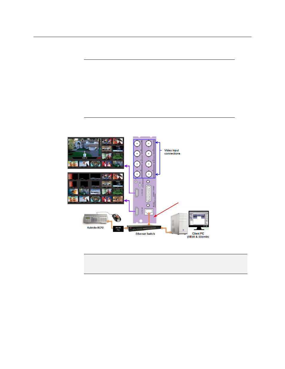
Cabling Diagram
Cabling diagram (showing KMV-3911 rear panel)
Step 2: Networking Setup
For the KMV-3901/3911 multiviewer to join a TCP/IP network, it must be configured with an
IP address, a network mask, a gateway, and a system name. In addition, a client PC must be
configured to communicate with the multiviewer (see
You must also configure any Kaleido-RCP2 units you may have ordered.
Notes
• If you do not press any button on the Densité frame local control panel, the
Densité controller will revert to its normal standby mode, and the selected
card's Status LED will revert to its normal operating mode, after 30
seconds.
• If you changed a parameter from the card’s control menu, but have not
applied your change (you did not press the SEL button on the local control
panel), once the 30-second timeout has occurred, the parameters will be
confirmed as if you had pressed the SEL button.
IMPORTANT
If you need to install or momentarily remove a Densité card’s rear module, make
sure to first remove the card itself from its slot.
Do not connect the
KMV-3901/3911 card to the
network until the card’s
networking parameters are
properly set (see