Grass Valley NV8500 Series v.3.5 User Manual
Page 147
131
NV8500 Series
User’s Guide
ule both slot 1 and slot 3. These slots are for the required, primary power supply modules. If
you are installing optional redundant PS8300s, install a module in both slot 2 and in slot 4:
Fig. 8-14: Power Supply Module Locations in an NV8300
Making Power Connections to the NV8576 or NV8576-Plus
Note: for the NV8576-Plus, you will execute this procedure for each frame.
1 Select one of the NV8300 power supply frames.
2 Facing the rear of the NV8300, connect one end of a WC0154-00 power cable to the DC Out-
put connector. (See Figure 8-12 on page 130.)
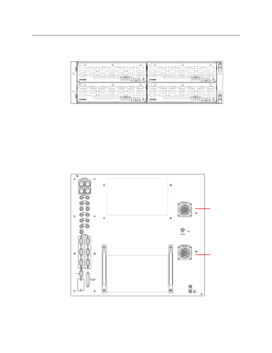
3 Facing the rear of the router frame, connect the other end of the WC0154-00 power cable to
Power Input 1:
Fig. 8-15: NV8576 Power Supply Monitor and Power Connections
PS 1 — Primary
PS 2 — Redundant for PS 1
PS 3 — Primary
PS 4 — Redundant for PS 3
Power Input 1
Power Input 2