Yaskawa SmartTrac PCIM Card User Manual
Page 14
SMART TRAC Genius PCIM Card
10
••
Installing the Smart Trac Genius PCIM Card Technical Manual 3554-0080
Connecting the Smart Trac Genius
Card to a Genius Network
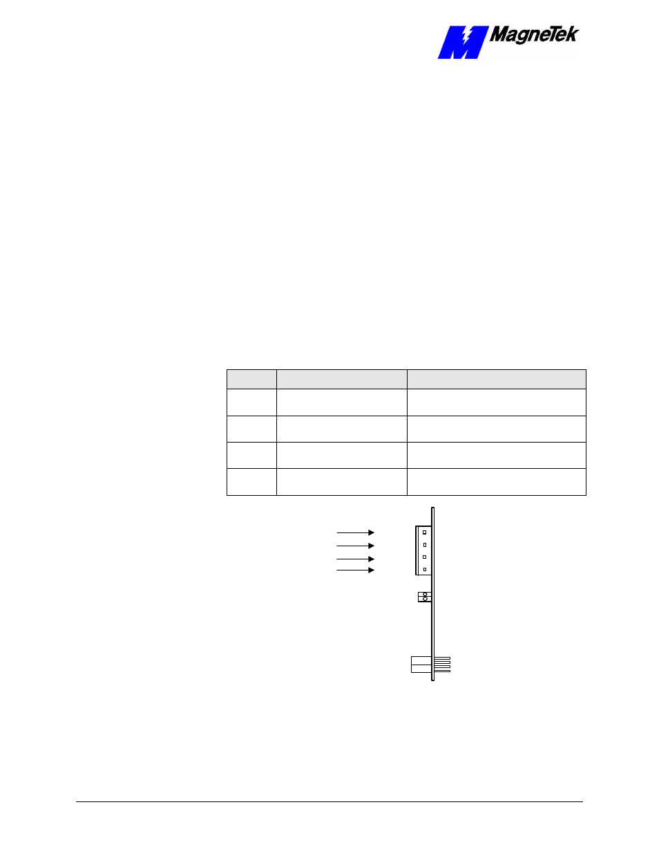
The Smart Trac Genius card connects to the Genius serial bus via a cable
installed at its 4-terminal connector
(see Figure 1)
. Terminals are labeled Serial
1, Serial 2, Shield In, and Shield Out.
You connect the Serial 1 and Serial 2 terminals of each Smart Trac Genius card
to the corresponding Serial 1 and Serial 2 terminals of the next device.
You connect the Shield In of each block to Shield Out of the preceding device.
You may leave the Shield In of first device and the Shield Out of the last device
disconnected.
When making bus connections, leave no more than two inches of exposed bare
wire. Insultate each drain wire with shrink tube to prevent the Shield In and
Shield Out wires from touching each other.
Installation must conform to Genius I/O product guidelines for the screening of
cables and components for the Genius serial bus. Cable construction must
conform to the pinout below :
Table 1. Pinout for Genius Network Cable.
Pin
Connect to:
Comments
1
Serial 1 of next block
By doing this, each device connects to the
previous and next devices.
2
Serial 2 of next block
By doing this, each device connects to the
previous and next devices.
3
Shield Out of previous block
By doing this, Shield Out of one device
connects to Shield In of the next device.
4
Shield In of next block
Not required if Smart Trac Genius card is
last device on Genius block.
Shield In of Prev Block
Shield Out
Shield In
Serial 2
Serial 1
Shield Out of Prev Block
X2
X1
Figure 2. Genius Network Connector.