Configuring the genius card, Configuring the smart trac genius card, Configuration – Yaskawa SmartTrac PCIM Card User Manual
Page 15: Default settings
SMART TRAC Genius PCIM Card
Technical Manual 3554-0080 Configuring the Smart Trac Genius Card
••
11
Configuring the Smart Trac
Genius Card
Configuration
You configure the Smart Trac Genius card for the Genius serial bus by either
accepting default values or changing them to suit your unique situation. The
values chosen at installation of the Smart Trac Genius card software driver must
match those set on the card.
Two switches on the Smart Trac Genius card allow user configuration of the
serial bus, memory locations, I/O Base Address, and enabling or disabling of
outputs.
Default Settings
The Smart Trac Genius card is shipped from the factory already configured for
the typical installation. Default Switch settings for SW1 and SW2 are described
below. Generally, you should accept these defaults and ensure the switches are
set correctly before installing your card.
A terminating resistor must be installed across Serial 1 and Serial 2 at both ends
of a Genius serial bus. Depending on the type of cable you use, you will need to
terminate with 75 ohm, 100 ohm, 120 ohm or 150 ohm resistors. When you're
connecting one end of the card to a 150 ohm serial bus, you use the 150 ohm
terminating resistor located onboard the Smart Trac Genius card.
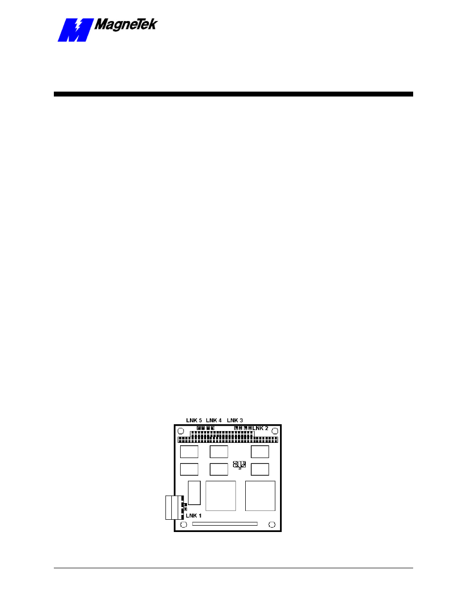
Figure 3. Genius Card Jumpers.
Bus Termination (LNK1)