Non-default settings for switch sw2 – Yaskawa SmartTrac PCIM Card User Manual
Page 19
SMART TRAC Genius PCIM Card
Technical Manual 3554-0080 Configuring the Smart Trac Genius Card
••
15
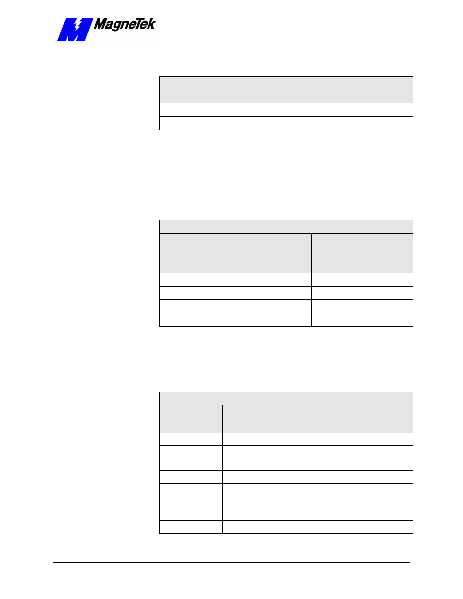
The Smart Trac Genius card may be set to either enable or disable outputs.
SW1 Optional Settings – Position 8 (Outputs)
Outputs
Position 8
Outputs Disabled (default)
0
Outputs Enabled
1
Non-Default Settings for Switch SW2
The Smart Trac Genius card uses two consecutive bytes of I/O space and 16
Kbytes of memory in the host system. I/O and memory locations must not
conflict with any other with other memory or device addresses in use. The Smart
Trac Genius card's switch SW2, positions 1-4, determine the starting address for
16 kbytes of memory that is used to store I/O data, for communications buffers,
and other information.
0 = Off 1 = On
SW2 Optional Settings – Positions 1-4 (Memory Location)
16Kb Data
and Comm.
I/O Starting
Address
1
2
3
4
C800
1
1
1
1
CC00
0
1
0
0
E000
1
0
0
1
E400
0
0
0
1
The I/O registers occupy 2 bytes of space in the host system. The application
software on the host system exchanges data with the Smart Trac Genius card by
reading and writing to the assigned I/O addresses. The host's I/O Base, or
starting, address is set using positions 5, 6 and 7 of SW2.
0 = Off 1 = On
SW2 Non-Default Settings – Positions 5-7 (I/O Base Address)
4-bytes I/O
Memory
Address
5
6
7
360
1
1
1
364
0
1
1
368
1
0
1
36C
0
0
1
3E0
1
1
0
3E4
0
1
0
3E8
1
0
0
3EC
0
0
0
Outputs
Memory Location
I/O Base (Port)
Address