Cable requirements, Removal of cladding and insulation, Preparation of test site – Ion Science Hydrosteel 7000 User Manual
Page 14: Installation, Hydrosteel 7000, Control equipment
Hydrosteel 7000 MANUAL
Ion Science Ltd
Page 14 of 43
Unrivalled Detection. www.ionscience.com
Hydrosteel 7000
Thermocouple
junction box
Thermocouple
1
0V
SCREEN
0V BK
+V RD
2
E
3
1
2
3
E
SCREEN
+V RD
0V BK
Red Connector
Blue Connector
4-20mA 1
4-20mA 2
0V
+V
+V
BK
RD
BK
RD
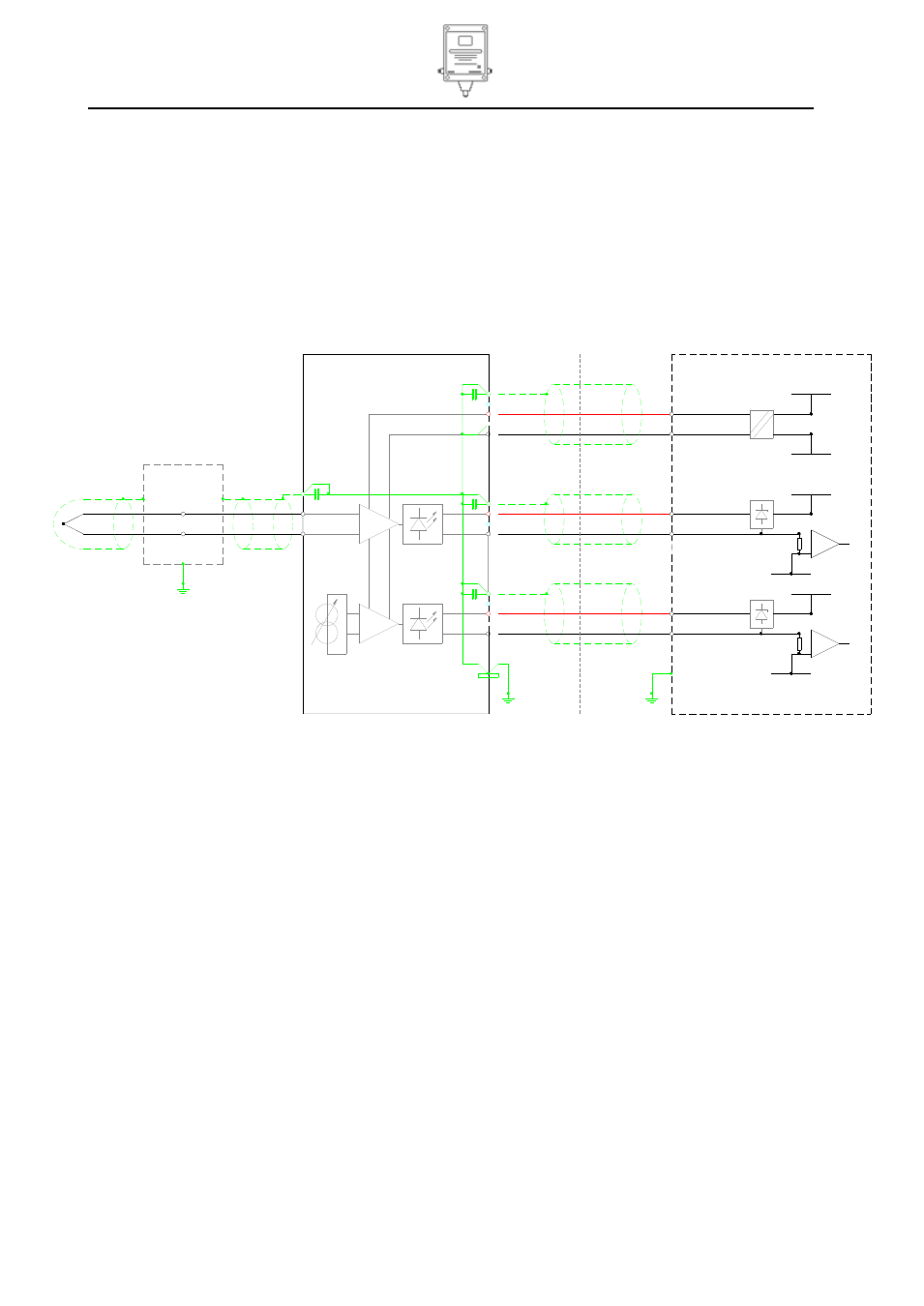
Electrical connections (IS) using galvanic isolator and alternative grounding
SCREEN
+V RD
0V BK
1
Yellow Connector
E
3
2
Power
+V
0V
RD
BK
Control equipment
SA
FE
A
RE
A
IS Galvanic
Isolator
Screens no longer grounded
at the control equipment end
Capacitors and Power OV shorted
to ground stud inside HY7K
JB earth
Note: JB earth and HY7K earth must be
equi-potential and have no more than 1 Ohms
resistance between them
HY7K earth
Installation
Use of Galvanic isolator and alternative grounding
Galvanic isolators may be used instead of safety barriers in the above circuit. If an isolated supply is used,
the supply at the instrument should be checked for AC noise. Measure the AC voltage between the 0 V and
the local earth. If there is AC noise this needs to be removed. It might be due to a faulty power supply or
induction of AC onto the cables. To remove the noise it might be necessary to ground the 0 V to an earth
point either in the control equipment or at the HY7K instrument. For electrically noisy environments the
optimum grounding is shown in the wiring diagram below. It is essential to follow the following key rules:
1. Screens may only be grounded at one end.
2. If the Power supply 0 V is grounded at the Hydrosteel then a suitable rated Galvanic isolator must be
used.
Cable Requirements
To meet the EMC compliance for immunity it is required that power and 4-20 mA current loops are supplied
with screened twisted pairs. Pairs should be individually screened with the screens terminated in the safe
area and to the terminals on the Hydrosteel 7000. (Note the Hydrosteel does not allow DC earth loops to
ground down the screens).
Removal of cladding and insulation
Hydrosteel flux measurement requires intimate contact between the probe plate and test surface, so it is
necessary to remove any insulation from the target sites.
For ease of access during probe installation, cladding and insulation should be removed from a 1 ft distance
from the centre of the site for flux monitoring. Additionally, if the probe is to be fixed with banding (to pipes
and vessels of less than 32” diameter), insulation and cladding must be removed from the entire
circumference of the vessel or pipe under test.
Preparation of test site
The surface should be free from ridges such as weld filets which could prevent the collector plate from
making intimate contact with the steel surface.
The identified test site surface should be at least 4”, in diameter, to accommodate both the probe and
magnetic thermocouple assembly. This surface should be free from rust and flaking paint which might
otherwise prevent hydrogen flux from exiting the steel surface.