Ion Science Hydrosteel 7000 User Manual
Page 21
Hydrosteel 7000 MANUAL
Ion Science Ltd
Page 21 of 43
Unrivalled Detection. www.ionscience.com
Installation
Conduit and tails do not rest against hot piping or equipment. As they contain thermoplastic
components that may be damaged.
WARNING!
Sample Conduit and tails must not be exposed to elevated temperatures above 100
C. These temperatures
can easily be experienced if the conduit or tails are in surface contact with high temperature process pipes.
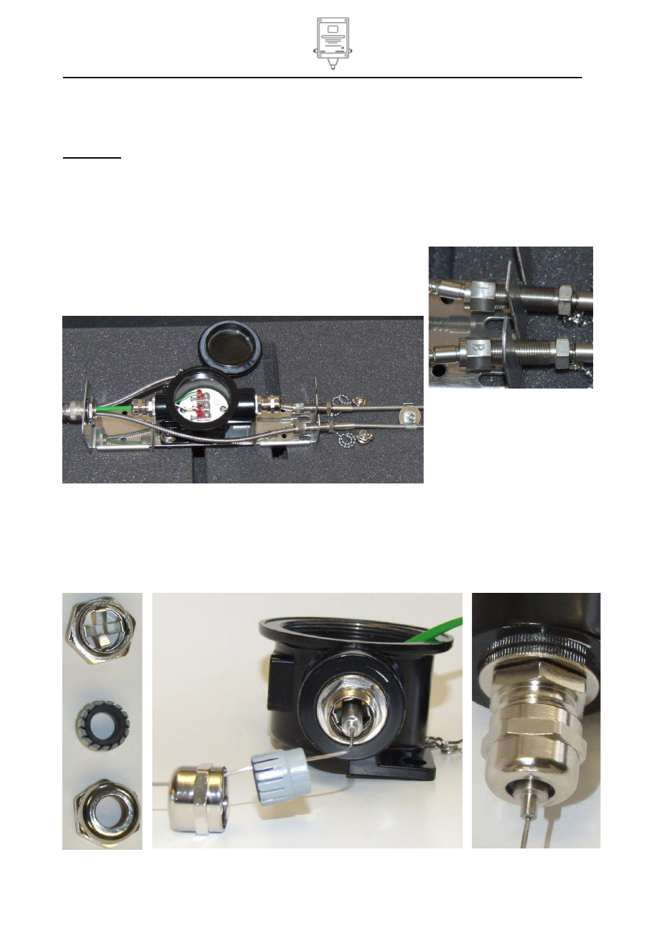
Connection of probes to sample conduit
Remove the probe caps. Simply attach the AT-S and ambient gas probes manually using the threaded
unions provided. Ensure that the correct capillaries are attached to the correct conduit cable
Tube with nut marked F (red tube or red cable tie) to AT-S probe
Tube with nut marked B (white tube or white cable tie) to
background probe.
Tighten the conduit nuts securely (1/8 turn) using 11mm
spanners.
Use cable ties through the slots in the probe bracket to hold
the probe connections in place.
Connection of thermocouple cables
The thermocouple lead terminates in two wires; these must be connected to the thermocouple cable in the
conduit at the thermocouple junction box. To maintain the continuity of the thermocouple screen, EMC
cables glands supplied must be used. Clamp the thermocouple pot into the cable gland. The internal
conductive spring tabs will make electrical contact with the thermocouple sheath and the pot will be
mechanically secured when the seal is compressed tight. Please see photographs below that follow.