Probe connection to hydrosteel 7000 – Ion Science Hydrosteel 7000 User Manual
Page 25
Hydrosteel 7000 MANUAL
Ion Science Ltd
Page 25 of 43
Unrivalled Detection. www.ionscience.com
Commissioning
Probe connection to Hydrosteel 7000
Termination of sample conduit with Han connector
1. Fit Harting connector assembly to the Hydrosteel 7000. This assembly is complete with a special Cable
gland.
2. Offer the sample conduit from the probe up to the Hydrosteel 7000 and mark the required length of the
spiral sheath where it will enter the cable gland on the Harting connector.
3. To maintain traceability of the pneumatic lines after cutting. Mark the tubes above the point at which they
are to be cut so that they may be differentiated (using a wrap of insulating tape is an ideal marking).
4. Pull the spiral conduit so that it extends by at least 30 cm. Cut through the conduit using a hacksaw. By
extending the conduit this ensures that the sub components (pneumatic tubes and thermocouple) have a
30 cm excess protruding from the conduit when it relaxes.
5. If it has not been possible to mark the tube or the marking has been
lost the lines must be traced through by blowing or sucking on the
tube.
6. Fit the M20 conduit adapter (1/HG-03) to the sample tube conduit.
7. The cable gland supplied may be one of two types. Type one uses a
sealing epoxy compound, type two uses a machined rubber gland. If
cable gland that use’s a sealing compound is supplied, then the
sealing compound should not be applied until the sample conduit has been completed to ensure correct
fit. The cable assembly should be fitted dry, following the fitting instructions supplied with the cable
gland. Split the cable gland and thread the pneumatic tubes and
thermocouple through.
8. Close the cable gland and tighten following the cable gland fitting
instructions.
9. Trim the nylon tubes and the thermocouple cable so that 10 cm
extends out of the end of the conduit gland. If any extra length is
required, the conduit can be compressed to reveal a greater length of cable and tubes.
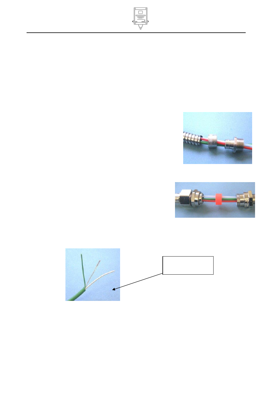
10. On the end of the thermocouple cable strip 30 mm of PVC outside sheath to expose screen and sub
cores.
11. Remove aluminium foil screen to the point of exit from the PVC sheath.
Cut back 30 mm of outer
sheath.
Remove aluminum foil