Cable connections – iSys i36 User Manual
Page 7
8
i36 ImageMaster User Guide
3
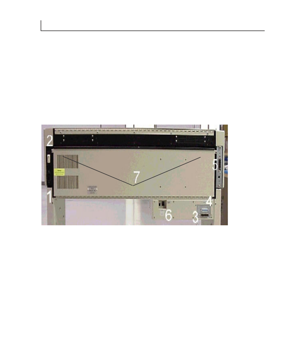
CABLE CONNECTIONS
The cable connections and power switch on the back of the i36 ImageMaster are
shown in Figure 1. They are:
1. AC power input.
2. Power (I/O) Switch.
3. PC/RIP Input (Centronics 36 pin).
4. PC/RIP Output (Centronics 25 pin).
5. Imager Input (Centronics 36 pin).
6. Network Input Port (with optional Internal Network Interface only).
NOTE: Also shown in Figure 1 are the two screws (7) securing the hinged back cover.
Figure 1. Back view of connections
The following instructions will allow you to properly connect the plotter.
AC Power Cable - 110/120 Volt
Plug the supplied AC power cable into the power connector (1).
Plug the other end of the power cord into a grounded AC outlet only.
NOTE: Avoid sharing a power outlet with noise-generating equipment.