System requirements, Specifications, Troubleshooting – Linkskey LKV-IOP08 User Manual
Page 9
ioPower User Guide Quick Installation
Rev. 1.41 Copyright© All rights reserved. Feb 2005
6
The Confirmation Dialog Prompt
You can also access the timer setting interface on the Global
Power Action Menu as well as to check the firmware version
of any specific bank of the daisy-chained ioPower units.
System Requirements
Operation
Mode
Requirements
Used with a
Host PC
•
a Win-based Host PC (with ioPower
Management Software installed)
•
Serial (RS-232) Cable for connection with
host
•
UTP cable (only for cascading multiple
units of ioPower)
Specifications
Model Name
ioPower
Input Voltage
100 ~ 240 VAC @ 50~60 Hz
Output Voltage
100 ~ 240 VAC @ 50~60 Hz
(Depending on power input)
AC Output
8 total
Front-panel control
8 Power buttons
Host connection
Serial RS-232 interface (DB-9)
User interface
Host PC / ioPower Management
Software
Cascade level
Up to 16 units
Cascade interface
RJ-45 (via UTP cable)
Max. current loads per port
6 amp per port
Current Overload
Protection
15 amp max.
Operating Temperature
0~45°C
Operating humidity
10~90% RH
Storage Temperature
-20 ~ 70°C
Storage Humidity
0~90% RH
Dimensions (L x W x H)
410 x 165 x 44.5 mm
Troubleshooting
An Alarm LED is Lit (Red)
In normal condition, the Alarm LED should never be lit.
However, when the Alarm LED is lit, it indicates that the
corresponding power output port is put out of function by a
hardware error, which prevents this port to power on or off.
If you see a lit Alarm LED, you should first disconnect the
device connected with it and then try to troubleshoot by
pressing several times its power button on the front-panel of
ioPower, to see if the Alarm LED still remains lit persistently.
If so, it indicates that this port is malfunctioning for good and
need technical service from your local dealer.
Port Error (unable to power on) Port Error (unable to power off)
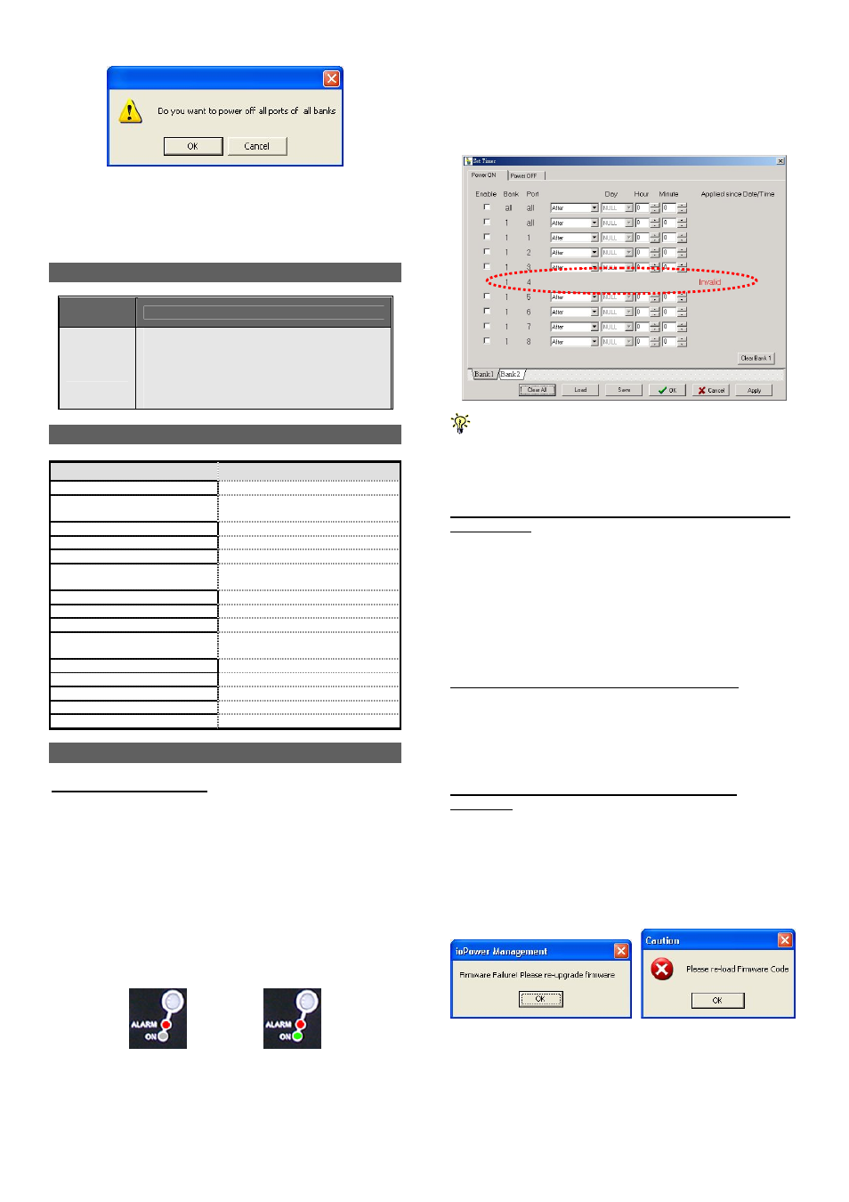
While an alarm LED is lit, the timer setting interface on your
ioPower Management Software will also show forth the
“invalid” message and block all sequent setting possibility on
that malfunctioned port.
When a port is currently scheduled with a Timer setting for later
power on/off, its alarm LED (red) will be flashing for a reminder.
Also when you perform a firmware upgrade on ioPower, all the
alarm LEDs will be flashing while it is still in process. In these
conditions, flashing red LEDs do not indicate a problem.
Current Overloads Warning - A Flashing Numerical LED
display (Red)
If the total current loads exceed 15 AMP-- the maximum
allowable current loads of ioPower--the numerical display of
the current loads (Red) will be flashing. If you see the
flashing Numerical LED display, it means ioPower is now
suffering form a current overloads. If that is the case, you
should try to shutdown some devices to keep the current
loads within its reasonable range.
Circuit Breaker Open Due to Current Overloads
If the total current loads exceed 15 AMP, the circuit breaker
device might be activated to physically break off the internal
circuit for safety and stop the function of ioPower. To restart
the unit, just press the Power Reset button on the back panel.
Firmware Upgrade Not Successful or Firmware
Corrupted
If your firmware upgrade has not succeeded or your firmware
is somehow corrupted and could no longer function anymore,
your current loads LED display will show forth a message
such as “OP”. If you see such message on your current
loads display, please upgrade your firmware once more or
check the integrity of your firmware code.