Fig.1c, Fig.2a fig.2b, Installation – Sealey SSC12710 User Manual
Page 4
3.2. UNPACKING THE COMPRESSOR.
3.2.1. to avoid damages and to protect the compressor during
transport it is placed on a wooden pallet, to which it is
secured by nuts and bolts. A cardboard cover is then strapped
to the pallet. All the shipping and handling information and
symbols are printed on the compressor packing. using a forklift
truck take the compressor as near as possible to the place
where it is to be installed.
Note! the machine must be
unpacked by qualified personnel using appropriate tools and
equipment.
3.2.2. release the strapping holding the cardboard cover onto the
pallet and with the help of a second person lift the cover up
and off the compressor as shown in fig.1B.
3.2.3. Inspect the compressor for any shortages or damage. If
anything is found to be missing or damaged contact your
supplier.
3.2.4. remove the four sets of nuts and bolts that secure the
compressor feet to the pallet as indicated in fig.1c.
3.2.5. Dispose of the packaging in accordance with local authority
regulations.
3.3. STORING THE PACKEd ANd UNPACKEd COMPRESSOR.
3.3.1. If the compressor is not to be unpacked immediately store it in
a dry place at a temperature between +5°c and +40°c and
sheltered away from the weather. If the compressor is not used
immediately after unpacking it, place sheets over it to protect it
from dust, which may settle on the components. the oil is to be
replaced and the operational efficiency of the compressor is to
be checked if it is not used for long periods.
fig.1C
4.1. The compressor must be installed as indicated in these
instructions. Any machine failure due to incorrect
installation will invalidate the warranty.
4.1.1 the compressor should be operated on a flat surface.
4.1.2. check the oil level, consulting the oil level inspection window.
use only synthetic oil (see maintenance section for oil
specification).
4.1.3. confirm the mains voltage corresponds with the voltage shown
on compressor data plate. Have a qualified electrician wire in
the compressor in accordance with section 1.1.
4.1.4. When fully installed, start the compressor and ensure that
everything is in good working order before operational use.
check the direction of rotation (see section 4.8.1) to
confirm correct wiring of 3-phase plug. re-check oil levels.
4.2. ROOM TEMPERATURE.
4.2.1. for correct functioning of the compressor the room
temperature must not be lower than 5°c or higher than 45°c.
4.2.2. If the compressor is operated at a room temperature
lower than the minimum value, the condensate could be
separated within the circuit resulting in water mixing with the
oil. the resulting deterioration in oil quality would fail to
guarantee the even formation of an effective lubricating film
between moving parts with the possibility of seizure.
4.2.3. If the compressor works at a room temperature higher than
maximum value, the compressor would take in air that is too
hot, which would prevent the heat exchanger from adequately
cooling the oil in the circuit, raising the working temperature of
the machine, thus causing the thermal safety device to trip,
which stops the compressor due to the excessive temperature
of the air/oil mixture at the screw outlet.
4.2.4.
The maximum temperature of the room is to be measured
while the compressor is running.
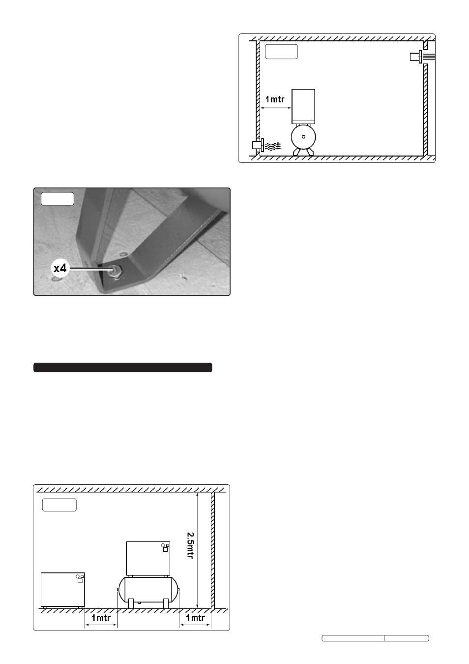
4.3. vENTILATION REQUIREMENTS.
4.3.1. the room must be provided with outlets that lead outdoors
near the floor and ceiling that will allow the natural circulation
of air. If this is not possible, install some fans or extractors (see
fig.2B) that guarantee an air flow rate 50% higher than that
taken in by the compressor (min. flow 2500m³/h). Ducts for the
inlet and outlet of the air can be used in unfavourable
environments. these ducts must be the same size as the
intake and delivery grills. If these ducts are longer than 3meters
contact the Authorised service centre.
4.4. SPACE REQUIREd FOR MAINTENANCE.
4.4.1. the compressor must be installed in a large room that is well-
ventilated, dust-free and sheltered away from rain and frost.
the compressor takes in a large amount of air that is required
for internal ventilation. A dusty atmosphere would in time
cause damage and inefficient performance. Dust drawn into
the machine will be taken into the air filter causing it to clog
rapidly. Incoming dust will also settle onto the components and
will be blown against the cooling radiator, consequently
compromising the efficiency of the heat exchanger. It is
therefore obvious that the cleanliness of the area in which the
compressor is installed is crucial for the correct efficiency of
the machine, avoiding excessive running and maintenance
costs. to facilitate maintenance and to create a favourable
circulation of air, the compressor must have sufficient free
space all around it as shown in figures 2A & 2B.
4.5. LIGHTING.
4.5.1. the compressor has been designed with the intention of
minimising areas of shade in order to facilitate the operator’s
interaction with the compressor both from a control and a
maintenance point of view. the lighting system in the area of
installation should be configured to further enhance this
interaction and should be considered as crucial for the operator’s
safety. therefore, the room in which the compressor is
installed must be neither under lit nor over lit, and without shadow
zones, dazzling lights or stroboscopic effects due to the lighting.
4. INSTALLATION
fig.2A
fig.2b
Original Language Version
ssc12710 & ssc12710D Issue: 3 - 23/02/12