Fig.12 – Sealey SSC12710 User Manual
Page 8
5.7. STOPPING THE COMPRESSOR IN AN EMERGENCY.
Press the emergency stop button on control panel (see section
5.2.) to stop the compressor immediately.
5.8. MANUFACTURER'S
CALIbRATION ANd SETTINGS.
the minimum setting pressure is:
mod/bar
set.pressure
10
8
Note! by disconnecting the
power supply from the external
switch the compressor is
completely without power.
the thermal relay is set according
to the following parameters
for the star/Delta version:
Power HP: (10)
Rated voltage 380/415v: (7,5 A)
disconnect the electrical power supply from the
compressor before opening the electrical cabinet.
the setting of trip switch 1 must not differ from the specification
above; if the trip switch should trip, check the input of the motor
of the compressor, the voltage on the line terminals L1+L2+L3
during operation and the power connections inside the electric
control panel and of the terminal board of the motor and
compressor.
5.9. CORRECT COMPRESSOR PERFORMANCE.
for the correct operational performance of the machine under
full continuous load at the maximum working pressure, ensure
that the temperature of the work area in a closed room does
not exceed +45°c. It is advisable to use the compressor with a
maximum service of 80% in one hour under full load in order to
ensure the maximum efficiency of the product.
6.2.2. the dryer comes provided with all necessary control, safety
and adjustment devices, therefore no auxiliary devices are
needed. A system overload not exceeding the maximum
operative limits can worsen the operational performance of
the dryer (e.g. high dew point), but it will not affect its safety.
the user must provide the dryer with a line protection and a
ground terminal.
6.2.3.
Use of the machine in safe conditions
this system has been designed and manufactured in
compliance with the European safety directive in force,
therefore any installation, use and maintenance operations
must be performed following the instructions contained in this
manual. Any installation, use and maintenance operation
requiring to access the internal parts of the dryer must be
performed by qualified personnel. the manufacturer will not be
liable in case of different uses or non-compliance with those
detailed in this manual.
6.2.4.
Control panel
the dryer is provided with an electronic system for parameter
modification. reset operations can be performed by means of
the digital control panel located on the front of the dryer. the
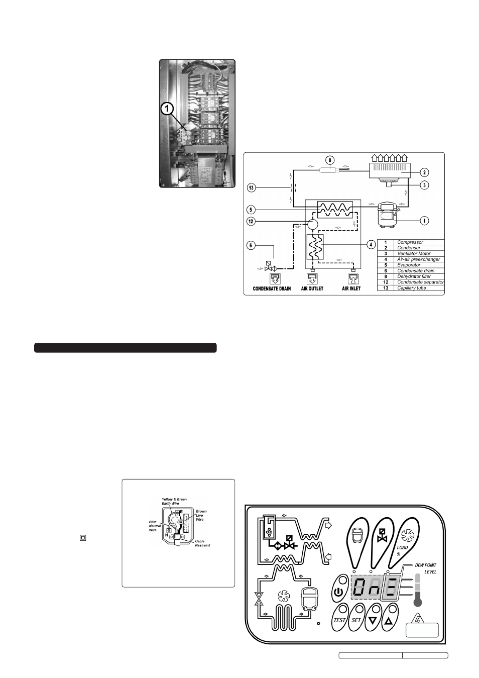
control panel illustrated in fig.12 is composed of 5 keys (on/
off, tEst, sEt, DoWn and uP) and a 3 digit display, with
three signalling LEDs indicated by icons.
WARNING! Ensure that you have read, understood and
apply Section 1 safety instructions.
6.2. PREPARING TO USE THE dRYER.
6.2.1
Functional description
this compact drying system, having a refrigeration cycle, has
been designed for the cost effective elimination of the
condensate contained in compressed air by cooling it down
to approximately +3°c. the operational principle of the dryer
is shown in the diagram below. the air output is virtually
humidity free, and the condensate collected in the separator is
discharged through appropriate draining devices. Before exiting
the dryer, treated air is counter current pre-heated by the air
entering the system thus avoiding condensation on the external
surfaces of the tubing and resulting in a more compact unit.
6. USING THE dRYER - SSC12710d ONLY
fig.12
Original Language Version
6.1. ELECTRICAL SAFETY.
IMPORTANT! The dryer mains cable is supplied without a
plug. Fit a UK 13Amp plug as described below.
Refer also to sections 1.1.1 to 1.1.5 in the compressor
electrical safety section.
6.1.1.
Important: Ensure that the voltage marked on the appliance
matches the power supply to be used and that the plug is fitted
with the correct fuse - see fuse below.
a) Connect the GREEN/YELLOW earth wire to the earth
terminal ‘E’.
b) Connect the bROWN live wire to the live terminal ‘L’.
c) Connect the bLUE neutral wire to the neutral terminal ‘N’.
d) After wiring, check that there are no bare wires, that
all wires have been correctly connected, that the cable
outer insulation
extends beyond the
cable restraint and
that the restraint is
tight. double
insulated products,
which are always
marked with this
symbol, are fitted
with live (brown) and
neutral (blue) wires
only. To rewire,
connect the wires as
indicated in diagram.
dO NOT connect
either wire to
the earth terminal.
6.1.2.
dO NOT pull or carry the appliance by the power cable.
6.1.3.
dO NOT pull the plug from the socket by the cable.
6.1.4.
dO NOT use worn or damaged cables, plugs or connectors.
Immediately have any faulty item repaired or replaced by a
qualified electrician.
FUSE RATING 13AMP
ssc12710 & ssc12710D Issue: 3 - 23/02/12