Sealey SSC12710 User Manual
Page 9
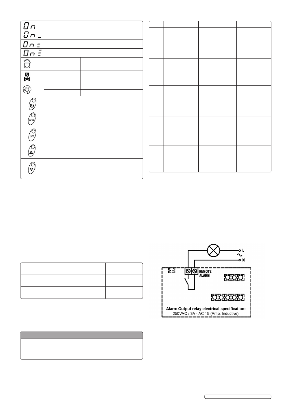
6.3. REMOTE SIGNALLING ALARM.
the dryer control board is equipped with a digital output for the
remote signalling alarm. this digital output is controlled by a
relay configured as normally open. When an alarm is detected,
this relay closes a circuit.
Proceed as follows to activate a remote alarm output:
6.3.1. the user must provide a signaller in compliance with output
relays electrical features (solenoid coil, light bulb, acoustic
signaller, ...).
6.3.2. Disconnect the dryer from electrical power supply, remove
cover and left side panel.
6.3.3. connect the signaller to the terminal blocks (see below).
The activation of the above function is at the user’s
discretion. The user must purchase all necessary
installation material. Any operation which needs
access to the dryer must be carried out by qualified
personnel.
6.4. bEFORE dRYER START UP.
Before starting the machine, make sure that all operating
parameters correspond to the nominal data outlined in this
instruction. the dryer is supplied already tested and preset for
normal operation, and does not require any calibration.
nevertheless, it is necessary to check the operating
performance during the first working hours.
6.2.4
Control panel (continued)
notE: when the controller is in off position, some parts of
the system remain live. therefore, for safety purposes,
disconnect the electrical power before performing any
operation on the machine.
6.2.5. conDEnsAtE DIscHArGE PArAmEtErs ProGrAmmInG.
Push the sEt key for 10 seconds to enter the parameters
configuration menu. the display will show in sequence the set
point value, the code of the first modifiable parameter (c8 and
its value). only if strictly necessary, use the uP and/or DoWn
keys to change the displayed parameter value. Press the sEt
key to store the previously changed parameter value or to
browse the parameters without changing them. 15 seconds
after the last performed operation, the controller will return
automatically to the normal operation mode.
COdE
CAUSE
OUTPUTS
ACTIONS
HtA
High Dew – point
value
(delayed alarm).
Alarm output on.
refrig. compressor
output off. fan
output on. Discharge
cycle standard.
resettable by
switching off the
control board when
dew-point returns to
preset range.
If it persists call our
service centre.
Ht2
Very high Dew –
point value
(immediate alarm).
LtA
Low Dew – point
value.
Alarm output on
refrig. compressor
output off.
fan output off.
Discharge cycle
standard.
Automatic reset
when
dew-point returns to
preset range.
If it persists call our
service centre.
PF1
Interruption or short
circuit on the Ptc
probe input line.
Alarm output on.
refrig. compressor
output off.
fan output off.
Discharge cycle
standard.
resettable by
switching off the
control board and
replacing the faulty
probe.
call our service
centre.
ESA
Energy saving
mode activated.
Alarm output off.
refrig. compressor
output off.
fan output off.
Discharge cycle
standard.
no action
necessary.
Automatic reset.
ES2
ASt
series of alarms
very close to each
other.
Alarm output on.
refrig. compressor
output off.
fan output on.
Discharge cycle
standard.
call our service
centre.
notE: changes entered for timing values will be effective only after
exiting the programming, while changes to other variables will be
immediately effective. Please remember that eventual changes to the
configuration parameters of the machine could negatively affect its
efficiency. thus, changes have to be arranged in collaboration with
the manufacturer.
6.2.6 AnomALY/fAuLt WArnInG
the controller is capable of recognizing certain types of
anomalies/faults occurring in the drying circuit. In such cases,
an alarm message will blink on the display, alternated to the
current dew – point value.
Note: PF1 has priority over all other alarm messages.
Original Language Version
this display means the unit is on with low load.
this display means the unit is on with normal load.
this display means the unit is on with normal - high load.
this display means the unit is on with high load.
LEd
LED status - on
compressor energised
LED status 'Blinking' Programming mode activated
LEd
LED status - on
condensate drain energised
LEd
LED status - on
speed of the fan = 100%
LED status 'Blinking' speed of the fan < 100%
on / off: Push for 3 seconds to switch on or off. When the unit is
off the display shows 'off'.
tEst - to activate a condensate drainage cycle, push for 3 seconds
during normal operation.
sEt - When pushed and released during normal operation it displays
the set point value (decimal). When pushed for 10 seconds it gives
access to the condensate drain parameters programming menu (c8 &
c9). Having set new configuration values, push again to store them.
uP - When pushed whilst setting the set point or configuration values, it
increases the displayed value by one unit per second, during the first 10
seconds then by 0.1 of a second thereafter.
DoWn - When pushed whilst setting the set point or configuration
values, it decreases the displayed value by one unit per second, during
the first 10 seconds then by 0.1 of a second thereafter.
When pushed
for ten seconds during normal operation, it starts an automatic test cycle
of the controller.
PARAMETER
dESCRIPTION
RANGE
SET
vALUE
C8
Delay between condensate
discharges
1 ÷ 999
(min)
1
C9
time required for condensate
discharge
1 ÷ 999
(sec)
1
WARNING FOR USERS:
It’s forBIDDEn to moDIfY tHE otHEr confIGurAtIon
PArAmEtErs of tHE ELEctronIc controLLEr WItHout
tHE sErVIcE cEntrE’s AutHorIZAtIon AnD
coLLABorAtIon.
ssc12710 & ssc12710D Issue: 3 - 23/02/12