Fig.3 fig.4 fig.5, Fig.6, Operation – Sealey SSC12710 User Manual
Page 5
4.6. UNSUITAbLE ENvIRONMENTAL CONdITIONS.
4.6.1.
dO NOT install the compressor in an environment where there
is a risk of fire and/or explosion.
4.6.2.
dO NOT install the compressor in an environment where there
is a risk that the machine may overheat. (maximum permitted
operating temperature 45ºc).
4.6.3.
dO NOT install the compressor in an atmosphere where the
humidity will be higher than 80%.
4.6.3.
dO NOT install the compressor at an altitude of more than
1000m.
4.6.4.
NOTE: this compressor is designed to work with a tank of a
specific size i.e. 270ltr. no liability will be accepted for any
related malfunctions or problems resulting from the compressor
being connected to a smaller tank. the compressor should not
be modified in any way.
4.7. POSITIONING THE COMPRESSOR.
4.7.1. once the position in which the compressor is to be installed
has been identified ensure that the compressor is set on a flat
surface. no special foundations or bases are required for the
compressor .
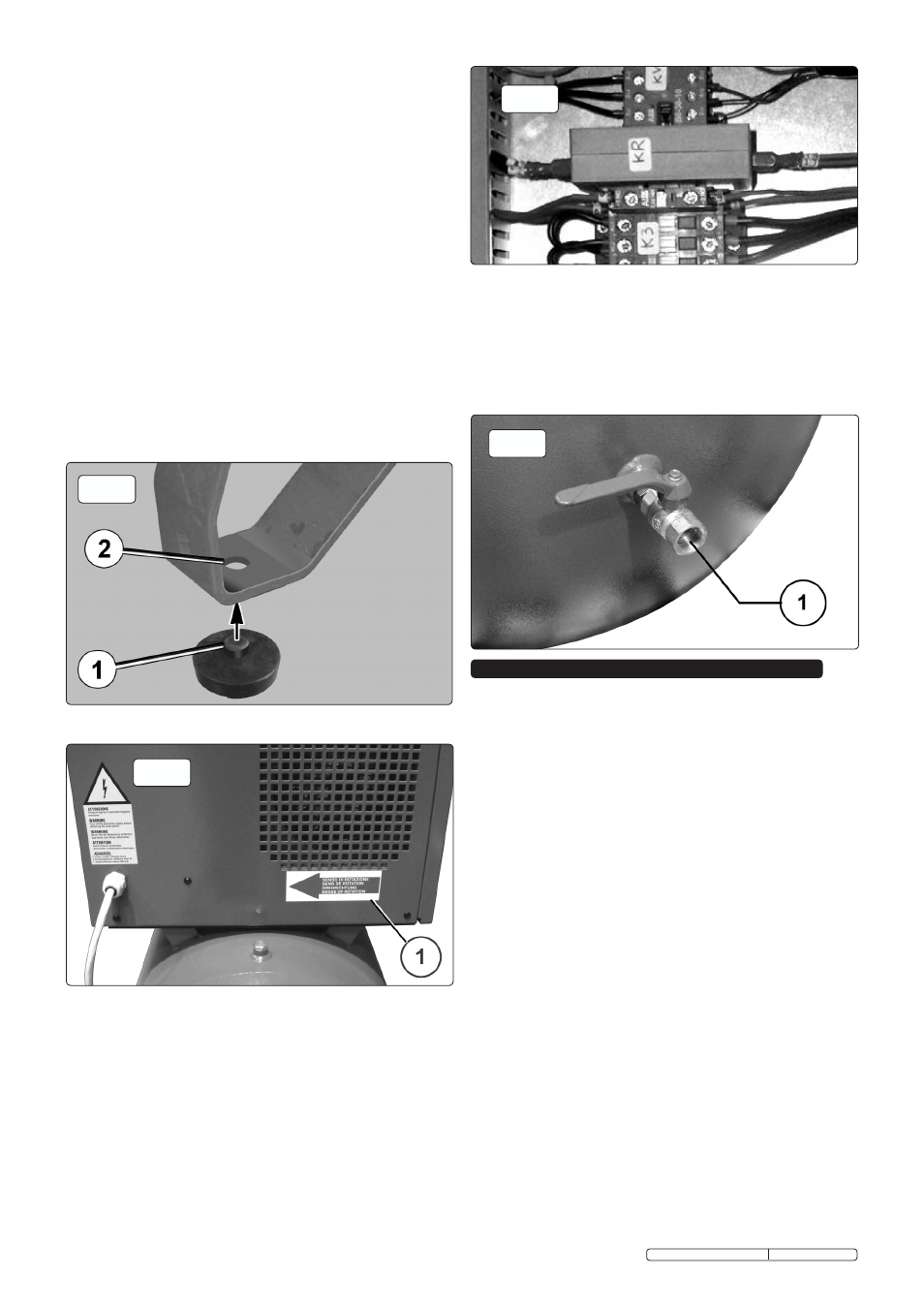
4.7.2. Lift the compressor using a forklift truck (forks at least 900mm
long) and insert the vibration-damping pads (1) into the
transit bolt holes (2) in the metal feet as shown in fig.3.
Do not sEcurE tHE comPrEssor rIGIDLY to tHE
fLoor.
fig.3
fig.4
fig.5
4.8. ELECTRICAL CONNECTION TO MAINS POWER SUPPLY.
Refer to section 1.1 (ELECTRICAL SAFETY).
4.8.1. cHEcK tHE rotAtIon DIrEctIon DurInG tHE
InstALLAtIon ProcEDurE. (see fig.4-1)
these 10 Hp compressors are equipped with a phase
sequence relay (Kr), see fig.5, that during every start up,
checks the rotation direction and, in case of wrong rotation
direction, stops the compressor (“AL3” error message on the
control panel).
disconnect the compressor from the
mains power, reverse two phases of the power cable on the
terminals for connection of the cable line and restart the
compressor. this procedure should be carried out by a
qualified electrician.
4.9. CONNECTING TO THE TANK COMPRESSEd AIR OUTLET.
4.9.1. When connecting to the tank compressed air outlet always use
pneumatic hoses with the maximum pressure characteristics
and cross section appropriate to the output of the compressor.
connect to the compressor using the 1/2" female BsP fitting
shown in fig.6-1. use hose of the same diameter (or greater)
as the compressor outlet. If a connection hose leaks or is faulty
never try to repair it but replace it with a sound one.
WARNING! Ensure that you have read, understood and
apply Section 1 safety instructions.
IMPORTANT! The use of extension leads to connect this
compressor to the mains is not recommended as the
resulting voltage drop reduces motor, and therefore screw
performance which may cause damage to your compressor.
NOTE: take care when selecting tools for use with the
compressor. Air tool manufacturers normally express the
volume of air required to operate a tool in cubic feet per minute
(cfm). this refers to free air delivered by the compressor (‘air
out’) which varies according to the pressure setting. Do not
confuse this with the compressor displacement which is the air
taken in by the compressor (‘air in’). ‘Air out’ is always less
than ‘air in’ due to losses within the compressor.
5.1. OPERATIONAL PRINCIPLE.
5.1.1. Air is drawn in through the air filter and passes through a valve
that controls its flow rate to the screw where it mixes with the
oil and is compressed. the air/oil mix produced by compression
is passed to a tank where an initial separation by gravity takes
place. the oil, being heavier, settles to the bottom. It is then
cooled and sent through a heat exchanger, filtered and injected
into the screw again. (the temperature is kept under control by
an electric fan that is directly controlled by a thermostat fitted
on the heat exchanger). the oil is required to reduce the heat
produced by the compression processes, to lubricate the
bearings and to maintain the screw lobes coupling. the air
is then sent through an oil separator filter to be additionally
purified from residue oil particles. It is cooled by means of
another heat exchanger producing a low temperature output
with acceptable oil residues (<3p.p.m). A safety system
monitors the crucial points of the machine and indicates any
abnormal conditions. the temperature of the air/oil mix at the
screw outlet is controlled by a thermostatic probe, which stops
the compressor if the temperature becomes too high.
fig.6
5. OPERATION
Original Language Version
ssc12710 & ssc12710D Issue: 3 - 23/02/12